| Home | Job | Pinball | Photo Album | Automotive | Press/Awards | Contact |

Improving X-10 signal Quality
There are a variety of ways to improve the performance of X-10 throughout a house. They include:
- Blocking signals from coming in and out of the home and a signal bridge.
- X-10 Active Signal Repeater.
- XTB High Power X-10 Transceiver
- Isolating Power Strip Loads (localized inductor blockers).
Whole House Blocker and Phase coupler
Background
In April 1995, I started
receiving X-10 commands from my neighbor down
the street. I decided to install a device to address this.
Prior
to this, I only had a 1uF capacitor bridging the phases installed in a
plug located at the outlet of my clothes dryer.
The Device
An advertisement from Worthington
industries
in an issue of Electronic House proclaimed the arrival of a new device
from ACT that promises to isolate your house from the rest of the
street
for $75.00. In addition, the unit also functions as a phase coupler. As
I will explain below, this latter function is very important for proper
operation of the blocker. After ordering one unit and setting up a
bench
test circuit at home, I was able to use my scope to measure that the
device
indeed attenuates X-10 signals by a factor of four to five. Technical
literature
from their company president Rick Scholl stated that if the amplitude
of
the offending X-10 command exceeds 100mVolts, two such filters will be
needed (one at each house's breaker panel) to block all signals.
Operating Principle
The device's principle
of operation is quite clever. In a conventional
design, you would have to insert an inductor of sufficient value and
current
rating in series with each incoming power phase. The size of such a
device
can be enormous. Instead of that approach, the ACT blocker is a
toroidal
transformer. The installer passes the neutral conductor to the house's
breaker panel thru a hole in the noise blocker and connects the
incoming
neutral and power phase connections to screw terminals on the device.
Note
that the device is not in series with the house, thus mega size
conductors
are not needed. The actual operation of the circuit is not 100% clear
to
me, but it functions roughly as follows: when an offensive signal is
detected
by the module, it somehow figures out its source (either from in or
outside
the house), and then magnetically induces a voltage of the proper
polarity
on the segment of the neutral cable that is inside the toroid's hole.
The
effect is that the signal will be cancelled out. For example, if there
appears 10mV of signal on phase A, it will be automatically be coupled
also to phase B. ACT's blocker then induces roughly 10mV of signal onto
the neutral, and the effect is that the house 'sees' no signal, since
there
exist an equeal amount of 'noise' on all three connections.

The whole-house blocker installed into the breaker panel
(right).
Note the thick uninsulated
neutral going thru the middle of it. The items clamped around
the two power feeds are the current
transformers for my power-line monitor.
Observations/Notes
- The device is small. It is approximately the size of a coffee mug. In my case, this allowed an inexpensive installation--right into the breaker panel. If it were much larger, it would require a much costlier and lenghtier installation. The electrician I hired needed one hour, a total cost of $80.
- In principle, there is no reason that the frequency response of the device be limited to the X-10 carrier. Perhaps the unit can / does function as an active high frequency fire wall for the house. In this case, it can add a side benefit of reducing line noise in general. I wonder then if this device can also be useful with the next generation of powerline carrier control such as CEBUS and Echelon.
- Leviton is also building a whole house block, and has been advertised for several months in Home Control Concept's flyer. As of Feb '95, this unit will not be available till late Summer '95, and is rumored to cost a few hundred dollars. I do not know how Leviton's device works, but from the drawings that I have, I do not see any thru holes. In addition, the Leviton device handles only two phases (up to 100Amps each), while ACT's can handle up to three (up to 200Amps each). I wonder if Leviton's device is just two big inductors.
- If the amount of attenuation of intruding signals is not sufficient, it would appear to be possible to install capacitors across the power lines on the meter side of the blocker to suppress these signals. I say this hesistantly as there are extraneous issues associated with doing this, so tread carefully.
- This device is very new. The serial number of mine is #109.
- Worthington's phone number is 800-282-8864. The part number is CP303, and it is UL listed.
The above whole-house
X-10 blocker/passive
coupler that I have used for
years works well, but there are one or two outlets in the house where
communication could be improved. I decided to install an
active
repeater to address this problem and purchased one from Worthington for
$85.00. I
installed the unit into the wall of my utility room from where all the
wiring in the home originates, and where the breaker panel is located.

The X-10 repeater from
ACT. It is installed into the wall of
my utility room
Each X-10 transmission consists of two identical halves. The CR230 repeater works by decoding the first half, and then sending out a copy of it which occurs concurrently with the second half of the transmission. As a result, the signal strength of the second half is much higher than the first. This can clearly be seen by my ESM1 X-10 Signal Strength Meter. I see a short bar blip on the display (from the original sender) followed by a long bar (amplified by the CR230). This is a very distinct signature as all previously seen signals produce two bars of the same length. It is not known if the CR230 phase locks onto the 120 KHz signal by the original sender, but if I were to design this box, I would certainly have done that. This would ensure that the signals of the CR230 and the original transmitter are in phase, and would not interfere destructively.
In my research of the device, I tried to find out if all X-10 receivers would work with just one copy (half) of the full X-10 message. This is because regions in the home that have weak signal would only 'see' one half of the command (the half that was amplified by the CR230). The general consensus on the newsgroups is that reception would work with all devices. Also, Phil Kingery from ACT advised not using both the CR230 and the CP303 in the same installation. I have not found this to be a problem.
In actual testing I have found seamless behavior, and communication over the whole house has improved. There are two particular breakers/zones that are problematic, and initial testing shows this has improved considerably. Further use will show if this is a good permanent solution (see Project log below).

Board inside the CR230. Note charred area at the bottom
(Image from 2020)
XTB-IIR
X-10 Signal Booster
One day in November 2008, I found that many of the X-10 signals in the home were not making it through. The problems were not related to jumping across the phases, but could extend to same phase. After lots of looking with my ESM-1 signal strength meter, I found that the two 5V switching supplies for my Vonage boxes were the signal disrupters. I isolated them with an inductor, but this event caused me to decide to look for any high power X-10 Boosters that were available. I found the XTB (X10 Transmit Booster), developed by Jeff Volp after some searching around.
I purchased a unit, and the parts kit is pictured below. His attention to detail is very impressive. The kit is complete down to the professionally printed decals, and the light tube for the LED.

Photo of complete kit to assemble an XTB-IIR.
Assembly took about 2-3
hours one
Saturday afternoon, and the unit worked immediately. It takes
a
fair amount of experience to assemble this kit as the component values
on the capacitors need to be carefully read. I must reiterate
how
impressed I am with this kit. The case was custom machined to
fit
the various parts. A very well designed system

Photo of assembled
unit. It fits neatly into
its
enclosure.
The XTB-IIR has two
modes of
operation. In the first, an X-10 transmitter (such as the
TW-523)
can be plugged into the outlet on its front cover, and any of its
transmissions are boosted to ~20Vpp levels (at the unit).
Incoming signals are also amplified. This is an impressive
and
clever feature. In addition, the unit also has TW-523
emulation,
and has an RJ11 jack for that purpose. Snapping in the
connector
from my home automation system, I now have a high-power transmitter for
the system.
The XTB-IIR is meant to be installed where both phases of the power line are available. However, this is not convenient for me, and I used it only in single phase mode. I have both a passive coupler (capacitor) and the ACT CR230 active repeater on my breaker panel.
The XTB-IIR is meant to be installed where both phases of the power line are available. However, this is not convenient for me, and I used it only in single phase mode. I have both a passive coupler (capacitor) and the ACT CR230 active repeater on my breaker panel.
Test Results
Before installing the
XTB-IIR, the
signal amplitude of the transmissions from my home controller varied
from 1Vpp (basement) to 0.1Vpp (upper floor, loft). It seems
like
the amplitude is greatly affected by the distance to the main breaker
panel. After the XTB-IIR was installed the amplitudes
everywhere
appear to increase by a factor of 2 or 3. Thus the basement
saw
amplitudes in the 2-3Vpp range, and the upper floor loft saw a signal
amplitude of about 0.3Vpp. This latter location has always
had
the lowest signal levels in my home, and it should have adequate signal
levels now.
Disclaimer: I have no financial involvement with Jeff's company.
I purchased an XTB, and he gave me a complimentary upgrade to an XTB-IIR.
Disclaimer: I have no financial involvement with Jeff's company.
I purchased an XTB, and he gave me a complimentary upgrade to an XTB-IIR.
In 2011, I added several high-tech electronic loads (HDTV, BluRay player, etc) and noticed another degradation in the X-10 performance. Measurements show that they all had several uF of capacitance on the power line, probably to suppress emitted switching noise. In the past, I have opened units like this and removed the capacitor on the power line, but I decided to install a localized high frequency block on these. I have a few dead X-10 wall switch modules, and these have an inductor in them to block the X-10 signal from being shorted out by the light bulb. I thought of the idea of installing these into the main power strip.

Inductor installed into the power strip.
The inductor has a measured value of 35uH, and they are wound with enameled 18 AWG wire. This is rated to 2.3 Amps. I installed one in each power strip after the circuit breaker per the photo above. The first application of one of these showed elimation of the particular communication problem. I installed one of these in each of the areas with lots of electronic appliances. In subsequent years, I have successfully used a 500uH, 2 Amp (part number M8274-ND at Digikey). This has a diameter of 0.56" and a length of 1.25".
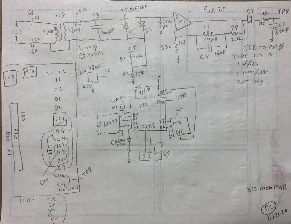
X-10 Line Signal Monitor
With all the time spent working from home in 2020 due to the COVID-19 virus, I decided to work on another microprocessor project. This time I wanted to build a device to monitor the amount of high frequency signal on the power line. I have had the ELK ESM1 for years, but it only gives a simple bar graph display.I based the front end of the circuit on the one in a wall switch module. This circuit has capacitors to isolate both sides of the power line and then uses a transformer to couple the high frequency portion over to the secondary ground. Since I had a few dead wall switch modules, I could readily salvage them for parts.

Initial prototype using a wall switch module.
As you can see from the schematic diagram, the signal from the coupling transformer is amplified by op-amp IC1. This is a non-inverting amplifier with a bandpass in the 120kHz region formed by L1 and C4. The output is then rectified and sent to a simple RC filter for amplitude measurement. From tests with a signal generator at the 120V plug, I measured a sensivity of 1.4mV per A/D bit. Thus each count from the 16F877 PIC's A/D means 1.4 mV of signal or noise on the power line.
There are two ways to view the signal from the power line. For the most direct way, I connect my mini-scope to the amplified and filtered analog signal. The scope is then triggered by the zero crossing signal from the TW523. This results in a very stable waveform and allows you to directly view the power line contents during the first msec after the zero cross.
The second way is to have the PIC sample the power line. In this method, the A/D on the PIC is used to average one msec worth of samples (about 60 samples) to provide 8 values representing 8 of the 8.3 msec of a half wave of the power line. In the latest firmware, the serial interface refreshes every two seconds the bottom line with this information. In addition, this sampled information is used to show the strength of individual X-10 commands, but sent and received.

Assembled X-10 monitor test
An
example output of the analog portion can be sampled at Test Point TPB.
This is shown on my mini-scope below. The zero cross occurs
one division from the left, and in this image the scope is sweeping at
1msec/div. Thus this shows the amount of noise/signal in one half
wave of the power line. The next zero cross occurs approximately
0.7 divisions in from the right as each half wave takes 8.3 msec.

The PIC that samples this and the output of a TW523 is accessible via serial line. This can be accessed on a PC by a serial terminal such as Tera Term. Below is an example session:

After the Power Up Banner is shown you can issue commands such as sending an X-10 command over the power line. Once that is completed, it will show the actual signal level that was achieved. In the example above, there are 83 units of signal when a 0 was intended to be transmitted and 188 when a 1 was sent. This difference of about 100 units means that the measured output signal was 140 mV. This gives the user a sense of the impedance of the power line at the local power outlet as the lower the impedance, the lower the achieved measured output will be.
The line after the transmit shows the result of a received command. The measured signal of each bit is shown (not including the "1110" in the X-10 header). After the numeric strength is displayed, a symbol is shown to indicate the polarity of the digital output line of the TW523 for that particular bit. The '-' is for a logic '1', and the '_' for a logic '0'. You can see for example that the first bit (after the header) is a '1' with a received strength of 164 units. The next bit should be then a '0', and that conforms with the display above, showing it had a line level of 94. The rest of the bits then follow, and finally the command is decoded and shown after the '>' symbol. This is an F-2 command. Lastly, it shows the highest level for the '0' commands, and the lowest level for the '1' commands. The larger the difference of these two levels, the larger the signal to noise ratio. Note that in this case the data was taken in an area with high noise levels. In a quieter location, the received amplitude for '0' bits is less than 10 units.
Finally, on the bottom line you see the Line Status, which is updated every two seconds. It continously refreshes 8 numbers, each of which is the signal level for a 1 msec time frame. This line thus gives snap shots of the received signal for 8 msec, or most of one half wave. The first sample needs to be small as this is when the X-10 signal is exchanged.
Other functions that can be seen in the Power Up Banner are 'b' for beacon mode. This causes the Monitor to continously transmit a pulse at the power line peak. This was meant to check for capacitors on the power line without interfering with the X-10 signal exchange. As of this writing, I have not used this feature very much, but that may change in the coming months as I use this device.
I built the unit to be portable but it looks like the best location for this is at my breaker panel. I used a spare Cat 5 cable to transfer the serial stream to my main home automation PC and can see the serial stream from anywhere with VNC. So I can use the system by walking around the house with a plug in transmitter. It occurred to me after installation that I should have built in two analog receivers, one for the A phase and one for the B. I will just move it from one phase to another.
July 2020 Update. I added a Bluetooth terminal to this device to allow wireless interaction. See here.
Links
- Article on filtering and blocking.
- April 15, 1995 - Installed whole house blocker. Since then there has been a complete cessation of outside commands. X-10 performance inside the home has been unchanged.
- July 2003 - Purchased and installed repeater unit into
utility room.
- December 2003 - One particular outlet that is mainly used for Christmas decorations has always been difficult to control by X-10. This year communication has improved, but is still not completely good. This outlet can now be controlled from the main control system, but not by all controllers in the house. All other communication problems appear to have been resolved.
- December 7, 2008 - XTB-IIR installed for use.
- January 28, 2012 - Installed several isolated power strips, after communication issues were found when adding several new electronic appliances. Rewrote this page to combine several blogs.
- June 29, 2020 - I accidentally noticed that the green light on the CR230 was not lit. Opening up the unit and found that the circuit board around D1 (a 1N5366B 39V 5W zener) was very charred. It tested shorted. I removed this unit from service and installed instead a Leviton HCA02. This latter unit also has a 'TEST' feature, where it sends out P-1 commands repeatedly.
- June 29, 2020 - Added the X-10 Signal Line Monitor with Bluetooth interface.