| Home | Job | Pinball | Photo Album | Automotive | Press/Awards | Contact |

The Roman Space Telescope (RST)
The follow-on legacy of the Hubble Project
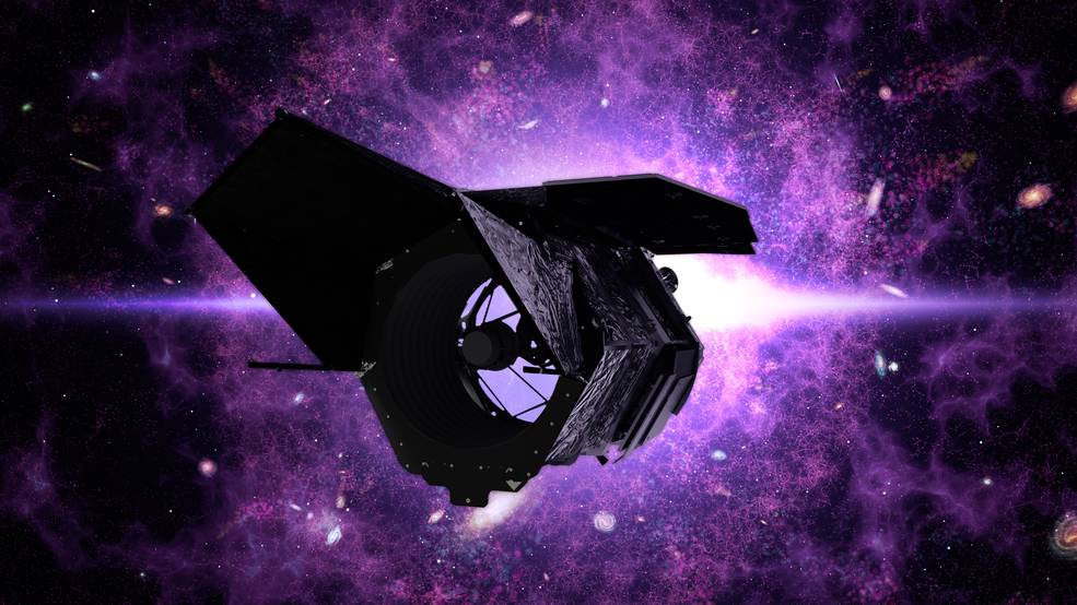
On January 10 2021, I was contacted by Dr. Ed Cheng (note spelling), who is one of the scientist working on RST. He wanted to know if I was interested in starting a side project that involved controlling LEDs for a in-flight calibration system for the space telescope. It sounded simple enough and I decided to give it a try. This calibration system was for the main camera of RST, called the Wide Field Instrument (WFI), which was being built by Ball Aerospace. They subcontracted out the calibration system, called the Relative Calibration System (RCS) to SDL. However, this system was behind schedule, and management wanted to have a backup in case they did not deliver. There was some political sensitivity, so this side project would be in secret and us two Dr Eds would work this quietly.
I designed and built a simple prototype, and found that my initial design concept was not going to work (using an LM117 as the current regulator). I learned from this and then switched to a more traditional op-amp based design and drew the schematic and did the simulation analysis. However, in April 2021, Ed told me the investigation we were doing was being cancelled as SDL showed good progress.
This changed again in June 2021 when SDL revealed at a monthly review to RST management that they were still behind schedule (they had been working on the RCS since Summer 2018). The SDL subcontract was cancelled, and I was tasked with resuming work on the design, which would now be renamed simplified RCS, or sRCS.
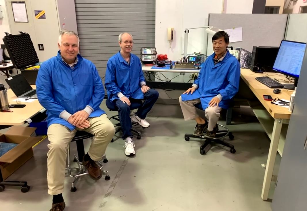
My role on sRCS would be as Electrical Lead, and I formed a small team of old friends. My alternate would be Roger Chiei, the FPGA and test GUI was built by Dr. Will Clement. Our electrical tech would be Ryan Fischer.
The electrical development team for sRCS. Left-right: Dr. Will Clement, Roger Chiei, me.
The reason SDL could not complete the design in the three preceding years was the large dynamic range and stability needed in the performance of the LED controller. Starting with a clean slate, I proposed a much simpler design that would be easier to package and build.
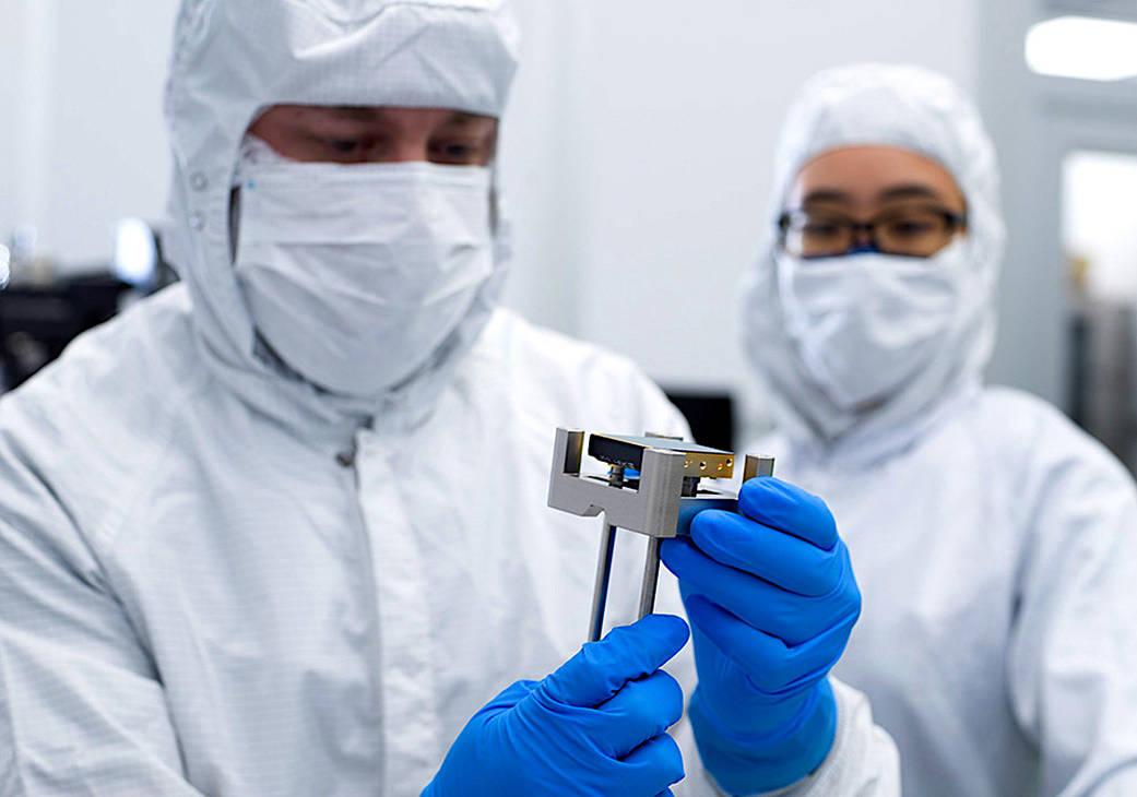
The main assembly house that was selected was the Peraton corporation in Beltsville, MD. That is the location of the image captured above. In addition to building the flight design, we also built an engineering unit (same board spin) to verify the overall concept. The main flight unit would have a one-time program FPGA, but the EDU would have a reprogrammable commercial equivalent, making code development practical.
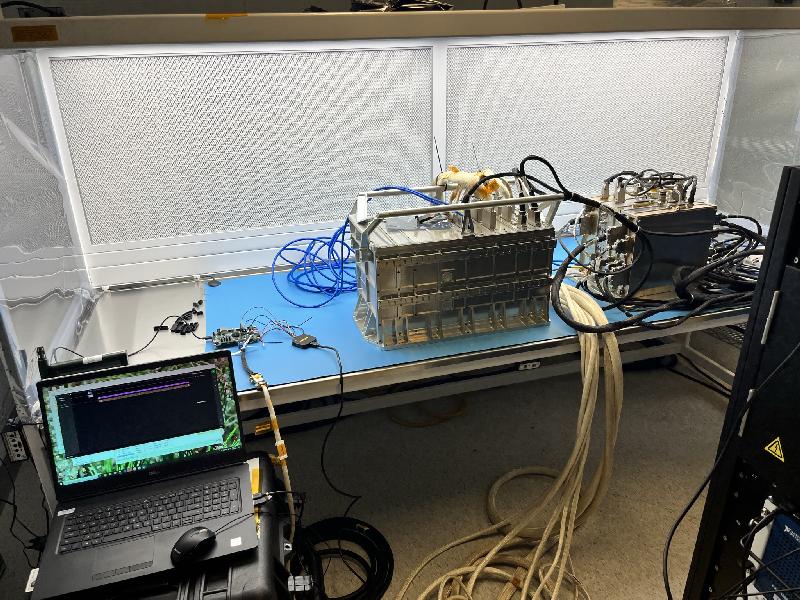
to once installed in the instrument. (Feb 2022).
Since the digital interface between sRCS and the instrument is a simple serial connection, I reasoned it would be worth it to build a simulator to start our code development. That test is shown above, the commercial board that hosts our FPGA code is the very small board on the edge of the blue mat above. It communicates with the large gold box that is at the center. This test was initially not successful, but we found the error. This made this test very valuable and worth while.
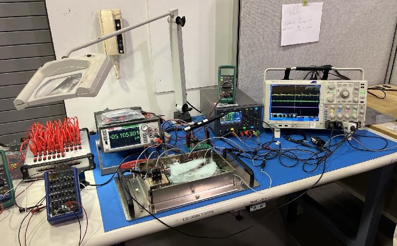
of the Engineering Development Unit (EDU). March 2022.
The first unit built would be the Engineering Development Unit (EDU) shown above on the test bench. We had to make some small modifications to tweak the design and this was done on the three flight units that would follow.
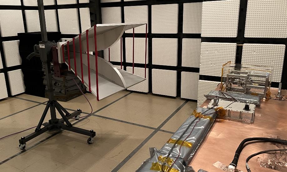
In the image above we assembled the complete non-flight system for an early EMI test. You can see the sRCS electronics as the gold box sitting on the copper bench on the right and this powers the integrating sphere that contains the LEDs. This sphere sits in a metal cage on the far right of the copper table.
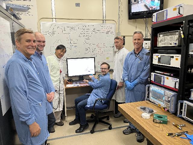
The test team doing the EMI test. The unit was so quiet that the
EMI team was impressed (September 2022).
of the LED sphere (October 2022).
More photos here in the Facebook album.
This is the unit we took delivery from Hawaii Aerospace.
Image released by NASA (October 2022).
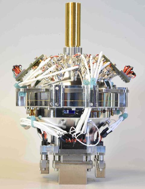
The integrating sphere above holds the 24 LEDs that comprise of the sRCS. These LEDs are powered by the sRCS electronics. The light is fired inwards and then come out of the gold cone at the top (and then onto RST's Focal Plane Array). The shortest wavelength light emitted is in the red color. So many of these cannot be seen by the human eye.
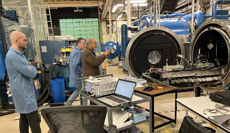
Both flight units were tested together in thermal-vacuum in the setup above. We were able to confirm good operation over the temperature that is expected on-orbit.
Delivery to Ball Aerospace (January 2023)
Additional photos here in Facebook album.
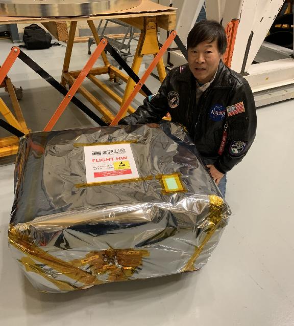
We took a break from work and headed to Aruba for the New Year holiday and then came back to ship the system to Ball Aerospace in Boulder, CO. The system was loaded onto a tractor trailer and was driven without stop (two drivers) along with a chase car to Boulder.
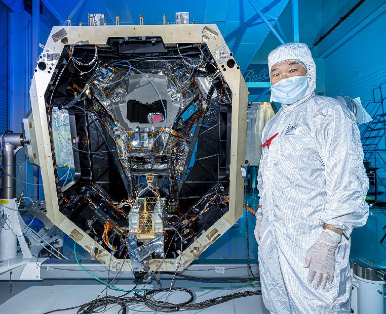
The red glow in the middle of the instrument is the light from the sRCS.
Image released by Ball and NASA.
Image of the team is here
(I am standing on the right next to the Instrument)
We delivered the system and oversaw the installation into the WFI instrument that is being built in the cleanroom in Boulder. You can see the two sRCS electronics units in the bottom part of the instrument above.
In this manner, we will go into space along with the instrument.
Image released by NASA.
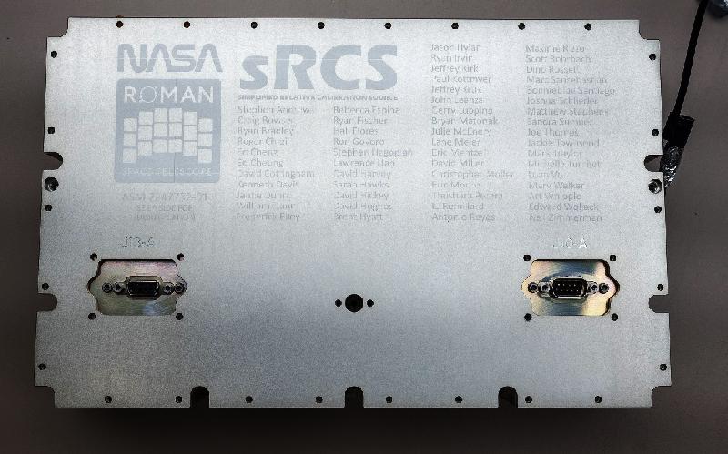
As part of the functional test, we turned the LEDs on, and you can see the red glow in the image above. Note that it appears in a curved opening, and that is the outline of the imaging detector of the Instrument. It turns out that my daughter is the one building this detector. You can see this curved detector array in the logo of the mission that is engraved on the cover of the electronics unit.
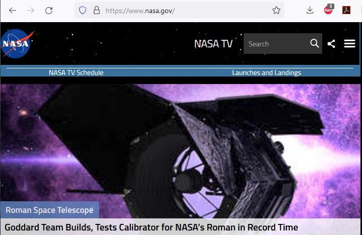
After our successful delivery to Ball Aerospace, we are
featured on the front page of NASA.gov:
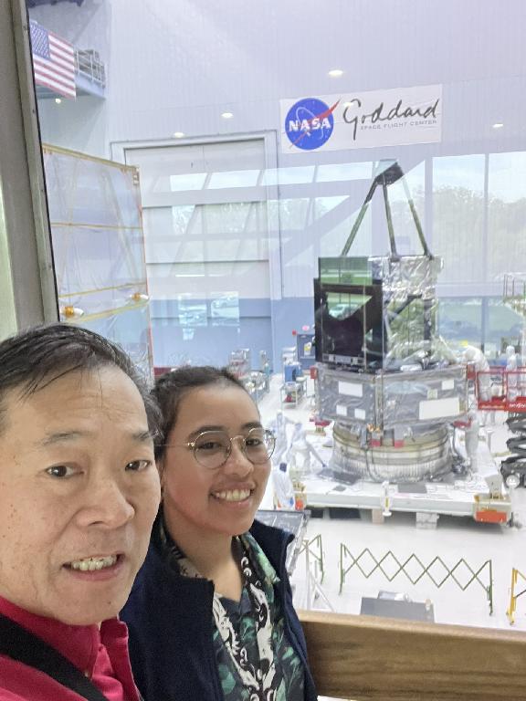
My daughter Stephanie (background) also works on Roman. She is
building the Focal Plane Array. Article on her work is
here at NASA.gov. Archive.
This is her posing in front of the non-flight development Focal
Plane Assembly. It has the array of 18 detector arrays.
I mentioned how her work relates to mine in my keynote speech
at the 2022 Gala event for the Netherlands-America
Foundation in Washington DC.
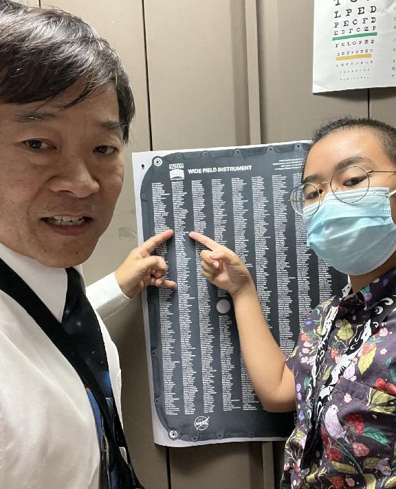
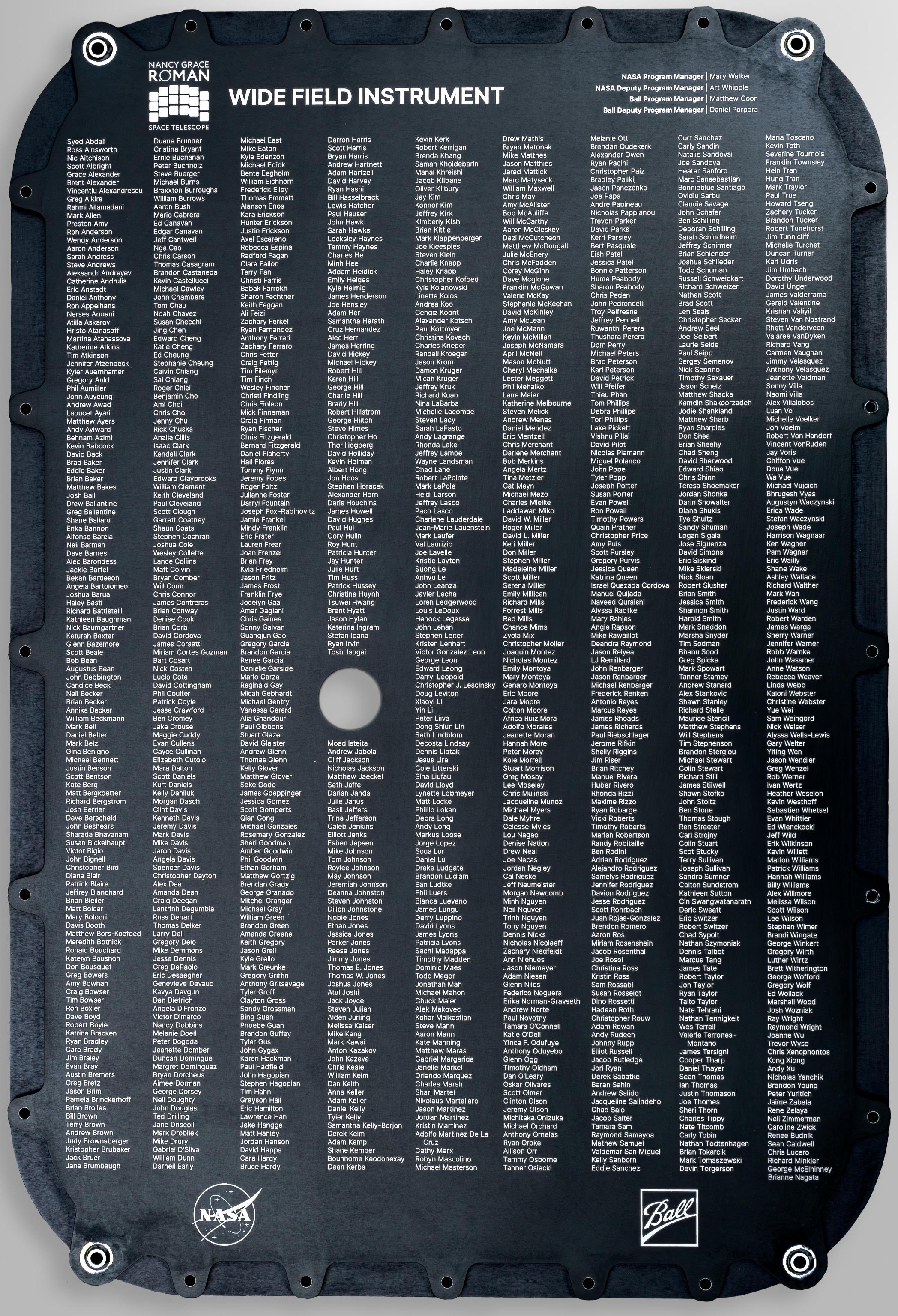
One of the panels on the WFI Instrument will have the names
of the team members on it and will fly in space that way.
Image here.
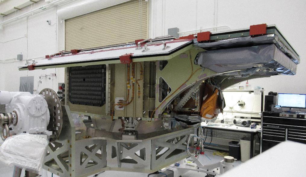
A photo of the WFI instrument at Ball Aerospace / BAE Systems showing
the location of the panel. Here the top panel is the outside radiator.
You can see the panel with our names is the dark on on the left.
(Image release for public on 3/5/2024).
In October 2024, the project released this video on the parts
coming together on the observatory. Click here for that video.
In January 2025, this article was released of the Spacecraft Integrated Payload Assembly (SCIPA) integration. This joins the main spacecraft bus with the instrument and mirror assembly.
In April 2025, we took a picture of the the Optical
Telescope Assembly stacked onto the SCIPA.
Since our start we have always been called "simplified Relative Calibration System", sRCS. Starting in the Fall 2025, we started to be refered to as only "RCS". Although there was a tinge of sadness at the unrequested name change, to the team I held the point that we were actually being promoted and were now considered the full fledged calibration system for the instrument. As the science team used our system more and more, they found other additional uses of our system, and it was nice to see us being accepted as a trusted part of the instrument.
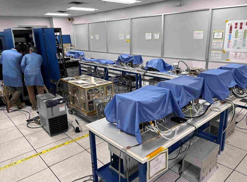
Our EDU integrated into the Roman Flatsat. The EDU is on the cart in
the middle of the room next to the brass looking box.
In August 2025, our test system and the non-flight Engineering Development Unit was integrated into the RST Flatsat. This system is essentially all the electronic units on a long table to represent an electrical and software test bench. It marks the end of our test program as a box.
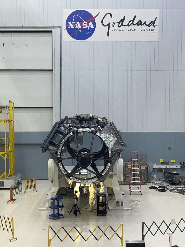
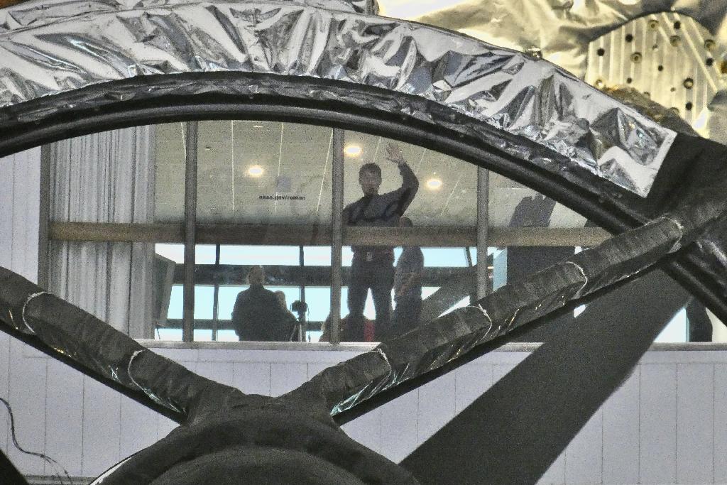
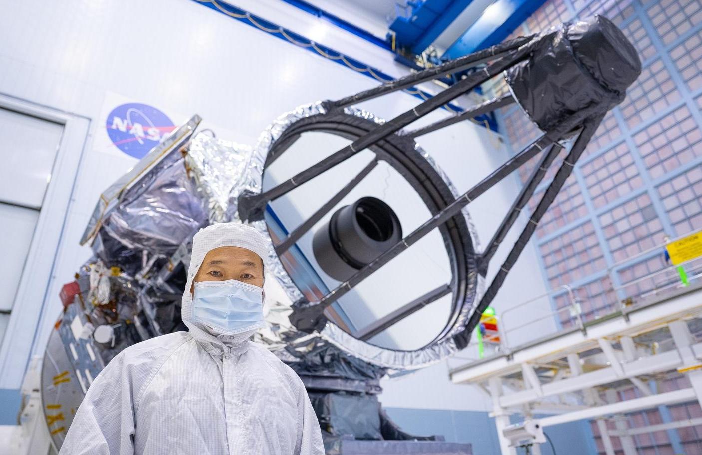
In December 2025, the spacecraft was tipped down and presented the perfect opportunity to take a mirror selfie in the primary mirror (similar to this one in the JWST mirror)
Telescope tipped horizontal and facing the
observation window in Bldg 29.
This is my reflection in the primary shot with my DSLR (60x zoom) and
inverted to be 'right side up'. You can see the ghost of the NASA
logo and "Goddard" in the glass (not intentional).
I assisted with the repair of SCE8 data lines and was able to take this
picture with the primary and secondary mirror exposed.
Image released for public use by NASA (Nov 2025)
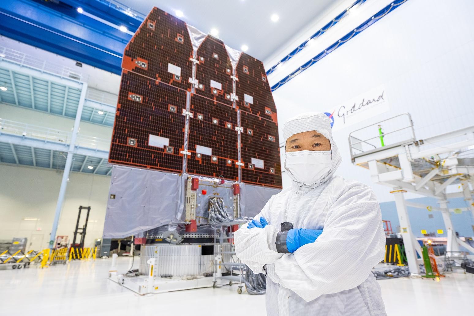
In front of the completed space telescope ready for shipment and prior to
the Pre-Ship Review in the Goddard clean room (April 2026).
Here we see Roman about to be encapsulated by the fairing
at the Kennedy Space Center. Post (August 2026).
Launch!
Was on time at 7:20am on August 30 2026.
Facebook album on this mission
Article on nasa.gov (archived)
NASA page on this mission