| Home | Job | Pinball | Photo Album | Automotive | Press/Awards | Contact |

Satellite Servicing Capabilities Office
Phase 2 of the Robotic Refueling MissionIntroduction
Following on the success of the Phase 1 of the Robotic Refueling Mission, and my amazing time on my Zero G flight, our project continues work on studying technologies to perform the repair and upgrading of satellites in space.
Phase 2 consists of several new innovative tools for the Space Station robotic system. The first is an inspection camera on the end of a snake-like extender called VIPIR. The second is to sense and detect leaks on Space Station called Ammonia Leak Locator (ALL). Lastly, we are also building a project called Raven, which will have a system of sensors to monitor how visiting spacecraft are arriving at the Space Station. This latter part is not really part of the robotic system, but it will still be a key part of Satellite Servicing technology.
VIPIR (Visual Inspection Poseable Invertebrate Robot)
The first of the new tools to be built is actually a miniature robot that looks like a long snake. There will be a miniature camera on the robot's end that will allow this system to perform inspections inside tubes and under thermal blanketing material. By sending it commands to guide it from ground control, the snake will be able to present views of hardware hidden behind other structure or thermal insulation. The long snake will be coiled up on a drum that is a prominent part of VIPIR. In addition, there are two more cameras to serve as means to use VIPIR or to inspect other parts of the Space Station.

Isometric rendering of the VIPIR tool. The tool has three cameras, one of which is on the end of a snake that is coiled up on the large drum (image approved by Jill McGuire).

The first test we do with the VEB is to find out if it can withstand the vibration of launch. We do that by putting the unit on a table that shakes the box so violently that the sound is strong enough to damage your hearing. This is the small vibration table at GSFC.

Next we put the VEB into a steel chamber and pump all the air out, and cycle the temperature from super cold to very hot. This simulates the harsh environment of space. In the bottom left you can see the panel of connectors that allow us to pass connections for power and comm into the unit we are testing.

The micro camera on VIPIR is super tiny. Only about 1mm thick,
it is shown here next to a dime.

Another subassembly is the Video Processing Unit (VPU) which is the system that
processes the signals from the micro camera on the robot head (image altered for IP).
It fits in the lid of the round drum.

We built up VIPIR in our clean area and we are dressed as you see here to maintain cleanliness and ESD safety of the flight hardware. This is a big moment (on 3/9/14) when all of VIPIR's systems are working together for the first time. Integration of all the systems (cameras, avionics, etc) took one day.

Photo from our gowning area. We reuse the garments for several days.

The assembled VIPIR! The micro camera is the bottom most camera, and has a ring of white LEDs surrounding it.

Another view of the VIPIR mini robot. The label reads: NASA GSFC (Goddard Space Flight Center) SSCO (Satellite Servicing Capabilities Office). It is mounted in its work stand in the upside down position from the rendering at the top of this page.
(these two photos by Jon Kraeuter).

Just like the VEB, we start the test of the VIPIR structure by putting it on a vibe table. This time on the large one that can shake an entire spacecraft.

The next test of VIPIR is in our EMI/EMC facility where we bombard the hardware with electromagnetic energy to see if it can stand the environment of space.
To maintain cleanliness of the hardware, we enclosed it in a clear box.

Finally, thermal-vacuum test of VIPIR. Again, just as in the case of the VEB (and VPU), we put the unit into a steel chamber, remove all the air, and subject it to the hot and cold of space. Shot with my wide angle attachment on my iPhone5, Jon and Matt are the two project leads on VIPIR.

On 3/23/14, we travelled by private jet to Ellington Field. The Learjet 35, being
small and light had an amazing accelleration on takeoff. In seconds we were
up to speed and took off. It was exhilerating.

Shot with my iPhone wide-angle attachment, you can see the cabin is small.
It also had no bathroom, and the flight took almost 4 hours. Two of
us (not me) had to go to the bathroom, and they <ahem> improvised.

The two hardware leads Matt and Jon stuffed themselves into the back
next to VIPIR's shipping container to show their dedication to keeping
it safe for the journey. Sharing hardware lead roles, they became known
as VIPIR's two daddies.

Cloud tops lit by the Sun.

Our flight path on the day of travel to JSC. From flightaware.com.

After arrival at JSC, we went to the SDIL software/hardware test facility.
This is the same one we have visited numerous times before. We passed
all tests successfully, which was a big relief for me. This would be the
final critical test for VIPIR.

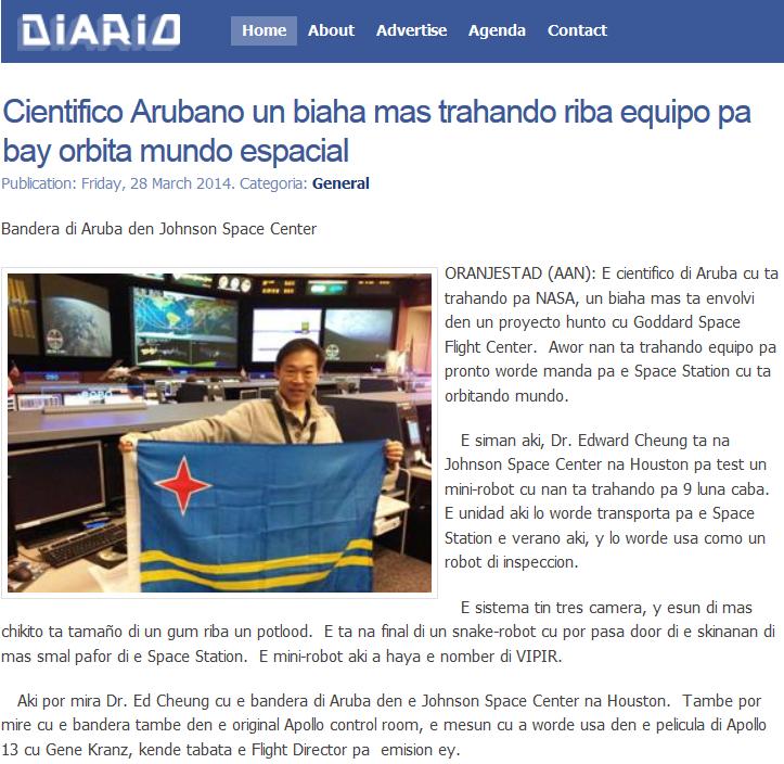
We visited Mission Control and shot this picture from the ROBO console
position from where the VIPIR will be operated. This picture later
appeared in the newspaper in Aruba, and would be the most
shared picture I have ever put on Facebook.

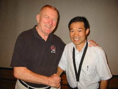
This is the original historically preserved Flight Control Room. The one from where
the Apollo missions were run. I sat in the same chair as Gene Kranz whom I met years before.

This hangs in the control room. It is a replica of the one on the Moon.

This picture shot with VIPIR and shows the core team that travelled to JSC.
I am on the right foreground.

I found time for some fun and exercise by visiting Fun City Skate. The rink is
very near the hotel and very convenient. The staff recognized me from
last summer when I was doing the Zero-G flight.

VIPIR was launched on the European Ariane 5 rocket on ATV-5 from French Guiana in July 2014. We all feel that VIPIR represents a new high water mark for mechanical and electronic sophistication, built in a very short time and with a small staff. I was very proud to have worked on it. Image from gizmodo.

This is the ATV5 on a hoist about to be mated to the Arianne rocket.
Photo by ESA. June 2014.

Launch was on 7/29/14 from Europe’s Spaceport in Kourou, French Guiana, heading for the International Space Station. Photo by ESA.

As a beautiful tribute to his new-born son, Ross Henry, one of my coworkers stored his son's initials on a test target that is part of the VIPIR hardware. It will be viewed by VIPIR during on-orbit operations.

ISS crewman Alexander Gerst inside the newly arrived ATV-5 (8/14). You can see VIPIR as the bottom right white bag (with the "4002" on it). Photo by ESA.
Unpacking and transfer into the Kibo/JEM Airlock (3/15).
At some point she lets VIPIR free float in the microgravity environment.

Once the airlock slide table is moved into the vacuum of space, Dextre (SPDM) gets ready to pull VIPIR out (top part of image). Operations occurred on 5/2/15.

A few hours later, VIPIR was pulled out by Dextre. The initial power on checkout occurred fine.
As I wrote on my Facebook page:

It may not look like much to others, but to us the view from the micro Camera in space meant the VPU was working correctly. It was a huge moment of celebration in the control room and the robotic lab. We will get a better image when we start using the micro camera in its intended optical arrangement.

View from the fixed camera that looks sideways at the micro Camera's exit port.

During on-orbit operations, we monitor things from two sites at Goddard. This is my view of the display consoles in the Goddard Satellite Servicing Control Center (GSSCC).

Other coworkers in the GSSCC. Mike (who flew with me on the Zero Gravity flight)
and Mark (right). Both mechanical engineers on RRM.

And this is the team in the Building 27N robotics lab during the night of the VIPIR commisioning. Matt (foreground) and Jon (right) are the two VIPIR lead. They accompanied me on the shipment with the private jet. After my shift in the GSSCC I visited the lab, and it was great to participate in the celebratory feeling there.

VIPIR works!

The next night, we pulled VIPIR out completely from the airlock and starting using it. View on the live ISS stream of VIPIR in space. At the time, we were over Asia looking West. VIPIR operations was very successful, and the Flight Director that night asked us to add more inspections to our operations.
Summary page on NASA.gov.
Article on TechTimes.
Article on NASA.gov on we were used to inspect
the big ISS robot arm.
ALL (Ammonia Leak Locator)
The second tool of Phase 2 is to address a problem that started in 2013, which is a steady leak in the ammonia system on Space Station. This fluid is used in the cooling system throughout the Space Station.

The blue circles show the flakes of ammonia drifting through space coming from the leak.
Video is here.
Ammonia is an extremely important resource on Station, and it is vital to find sources of the leak in order to repair it. In addition, there may be future leaks of other kinds. To address this type of problem, the Space Station program asked us to build a detector for any kind of gas that may be drifting in the super thin atmosphere around it. This is done by basing the design of the ALL on a Residual Gas Analyzer (RGA), which makes it very sensitive and allows it to detect the atomic weight of the of gas that is leaking and the quantity.

At a meeting at the Johnson Space Center in Houston where I presented
the electrical design of the ALL. The unit here is a 3D printed version of the flight unit. The robot grabs the gold cube shape on the far left, and the intry port of the gasses is the tube on the right.

Meetings at the Johnson Space Center in front of the Software Control Board.
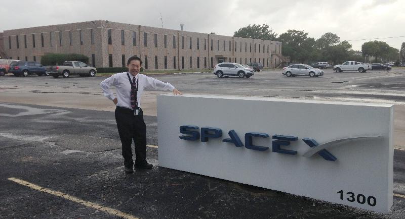
At the SpaceX offices in Houston Texas. At one point we were
going to launch on this rocket.

I do a fair bit of travel, and Hertz is my car company.

The Detector Electronics Box (DEB) in March 2014.

The commercial sensor from SRS. In our application, we folded this sensor into two halves. The break is right in the middle by the sensor tube interface.

The first flight unit built up and taped with the reflective tape for thermal protection. This tape is very fragile, so we leave the orange protective layer as long as possible.

The sensor sitting on motorized stage to see how it reacts to leaks.

Stephanie wrote the software that controls the motorized stage as one of her summer intern projects in 2013. Here it is in use.

The second test is with the unit in our electrical emissions and tolerance facility. This is where we see if it produces any electrical noise, and if it is tolerant to the noise environment on Space Station. Since it can only operate with the intake tube at vacuum, we rand a vacuum pump in the EMI chamber. This vacuum plumbing has a glass window so that RF energy can move in and out of the intake tube so that the test is accurate (May 2014).

The flight Leak Locator is hooked up to a cross-shaped manifold that has a clear glass window in the front part to allow the passing of RF energy in order to have an accurate test. We also used ceramic isolators in the manifold, which made the setup fragile.

This is the view inside the glass window of the vacuum piping system. You can see the glowing filament of the Leak Locator Sensor.

Just like with VIPIR, the unit launches in a protective bag inside the launch vehicle. As a result, we also do our vibration test in a flight-like bag (June 2014).

The completed flight unit, just before shipment. The two particle intake ports are covered by the brown plastic covers. These are removed by the astronauts once the unit arrives in space.

I saved one of the covers as a souvenir of the Leak Locator project.

The complete flight unit. This is the last picture I would take with it as would be shipped to Houston the next day.

The viewing area was the blue dot in the above image. The Launch Pad is
only 2 miles away on the beach in the southeastern direction.

Our passes for the launch viewing as VIP. There were about 300 people
attending the first day. About 125 on the second day.

Front gate of the WFF.

The VIPs met at the Chincoteague Community Center to hear the safety briefing and to
board buses to the launch site.

We had a small group from SSCO that came the first day. One the second day, there were
only 8 of us.

At the relatively small count down clock at the launch site. Location.

I borrowed the project's camera for the day and set it up on a small tripod.

Pano of the launch viewing area. Rocket on the coast on your left, and the
bleachers on the right. There were tents with food and tables behind the
bleachers.

Sunset was beautiful. The initial launch windows were near midnight, but the later
ones were near sunset.

I shot the launch stack through a pair of regular binoculars and my iPhone 6.

When the above image is blown up, you can see a surprisingly good image. This shot
from my iPhone 6 through a binocular lens.

Compare the above with the image from the Nikon Coolpix P520.

First few seconds of launch went fine....

...then we had the launch failure.
Youtube Video shot by me of the launch failure.

Second flight unit ready for delivery (January 2015)

The second and successful launch was on December 6, 2015 aboard an Atlas V on the OA-4 mission. It was very cloudy and we were limited to seeing it from the badging station outside of the KSC gate. As a result, we saw no view of the launch. Great pictures on the spaceflightnow.com site. Instead, we used the time to explore Diagon Alley (Harry Potter's world) at Universal Studios.

The Cygnus vehicle arrived and was grappled on 12/9/15 at Space Station.
Image from here. ALL was then brought inside and stowed in storage.

On November 29, 2016 we saw our first operational use on ISS.
By then, we had been renamed the Robotic External Leak Locator, or RELL.
This fuzzy screen capture shows the instrument being held by the
SPDM arm and taking samples of the vacuum environment.
Operation went perfectly with expectations and we saw some
useful readings that corresponded with venting events.

A close-up picture of RELL (middle) being held by the SPDM (lower right).
By scanning around with the robot arm, we were able to locate
the ammonia leak conclusively.

Picture of RELL on the end of the two robot arms with the Earth as backdrop.
Over the course of its use on the ISS, RELL has received the following NASA
team awards:
Group Spaceflight Awareness Award (May 2017)
JSC Group Achievement Award
Agency Silver Achievement Medal (June 2018)
It is very unusual for such a small project to receive so many awards. I am proud to have been part of this team.
Following on the success of the Phase 1 of the Robotic Refueling Mission, and my amazing time on my Zero G flight, our project continues work on studying technologies to perform the repair and upgrading of satellites in space.
Phase 2 consists of several new innovative tools for the Space Station robotic system. The first is an inspection camera on the end of a snake-like extender called VIPIR. The second is to sense and detect leaks on Space Station called Ammonia Leak Locator (ALL). Lastly, we are also building a project called Raven, which will have a system of sensors to monitor how visiting spacecraft are arriving at the Space Station. This latter part is not really part of the robotic system, but it will still be a key part of Satellite Servicing technology.
VIPIR (Visual Inspection Poseable Invertebrate Robot)
The first of the new tools to be built is actually a miniature robot that looks like a long snake. There will be a miniature camera on the robot's end that will allow this system to perform inspections inside tubes and under thermal blanketing material. By sending it commands to guide it from ground control, the snake will be able to present views of hardware hidden behind other structure or thermal insulation. The long snake will be coiled up on a drum that is a prominent part of VIPIR. In addition, there are two more cameras to serve as means to use VIPIR or to inspect other parts of the Space Station.
Isometric rendering of the VIPIR tool. The tool has three cameras, one of which is on the end of a snake that is coiled up on the large drum (image approved by Jill McGuire).
The
photo above shows a rendering of VIPIR. The snake like robot
will
be coiled on the large drum, and it will extend from the circular star
opening in the top right of the image. Details of this snake
robot are proprietary to NASA, and will not be shown. On the
far
right in the image is a new camera with motorized zoom and focus.
Finally, in the middle of the image is the remaining camera,
which is identical to cameras used on Phase 1, and provides a right
angle view to best ensure that the VIPIR is positioned properly to
deploy the snake robot. All the electronics to control the
VIPIR's motors, cameras, lights and sensors will be contained in the
dark grey box, called the VEB. This latter box also has the
umbilical connector that the SPDM robot uses to power and communicate
with VIPIR. As the Electrical Lead, I and my team am
responsible
for the entire electrical and electronic design.
To ensure that the hardware we build is compatible with Space Station's electronics, we regularly test our preliminary and then final versions at the SDIL test bed at the NASA Johnson Space Center in Houston.

Almost
all of the electrical system that runs the motors, cameras and lights
on the VIPIR are housed in this unit, called the VEB. Here it
is
completely assembled and represents the work of a large team in itself.
The SPDM robot on Space Station plugs into the doors on this
face
to power up and communicate with the VIPIR.To ensure that the hardware we build is compatible with Space Station's electronics, we regularly test our preliminary and then final versions at the SDIL test bed at the NASA Johnson Space Center in Houston.
At a test at the SDIL
facility at the Johnson Space Center on (7/13).
This facility is a copy of the Space Station so that new
hardware
can be tested on the ground. We have come to this facility
numerous times in the past.

Since the tool will be
handled by the SPDM robot, we test near the Robotic Work Station (RWS)
that is an identical copy of the
one in space on the Station.
After all the critical initial tests were done such as SDIL, we underwent our Peer Review in September of 2013, and then CDR in November of 2013. That later review marks the phase of the project where we start flight hardware builds.

After all the critical initial tests were done such as SDIL, we underwent our Peer Review in September of 2013, and then CDR in November of 2013. That later review marks the phase of the project where we start flight hardware builds.
The first test we do with the VEB is to find out if it can withstand the vibration of launch. We do that by putting the unit on a table that shakes the box so violently that the sound is strong enough to damage your hearing. This is the small vibration table at GSFC.
Next we put the VEB into a steel chamber and pump all the air out, and cycle the temperature from super cold to very hot. This simulates the harsh environment of space. In the bottom left you can see the panel of connectors that allow us to pass connections for power and comm into the unit we are testing.
The micro camera on VIPIR is super tiny. Only about 1mm thick,
it is shown here next to a dime.
The
main feature of VIPIR is a tiny micro camera that is only about 1mm in
diameter, thinner than a dime. Contained in this small space
is
the optics, the imager and the electronics needed to send the image
electronically to the VPU shown below.
Another subassembly is the Video Processing Unit (VPU) which is the system that
processes the signals from the micro camera on the robot head (image altered for IP).
It fits in the lid of the round drum.
The
system above is the VPU, which processes the signals from the micro
camera into conventional video. It represents one of
the
most intricate and complex circuits I have ever developed.
The
round shape of the printed circuit board and the frame makes it look
like the arc
reactor from Iron Man.
We built up VIPIR in our clean area and we are dressed as you see here to maintain cleanliness and ESD safety of the flight hardware. This is a big moment (on 3/9/14) when all of VIPIR's systems are working together for the first time. Integration of all the systems (cameras, avionics, etc) took one day.
Photo from our gowning area. We reuse the garments for several days.
The assembled VIPIR! The micro camera is the bottom most camera, and has a ring of white LEDs surrounding it.
Another view of the VIPIR mini robot. The label reads: NASA GSFC (Goddard Space Flight Center) SSCO (Satellite Servicing Capabilities Office). It is mounted in its work stand in the upside down position from the rendering at the top of this page.
(these two photos by Jon Kraeuter).
Just like the VEB, we start the test of the VIPIR structure by putting it on a vibe table. This time on the large one that can shake an entire spacecraft.
The next test of VIPIR is in our EMI/EMC facility where we bombard the hardware with electromagnetic energy to see if it can stand the environment of space.
To maintain cleanliness of the hardware, we enclosed it in a clear box.
Finally, thermal-vacuum test of VIPIR. Again, just as in the case of the VEB (and VPU), we put the unit into a steel chamber, remove all the air, and subject it to the hot and cold of space. Shot with my wide angle attachment on my iPhone5, Jon and Matt are the two project leads on VIPIR.
On 3/23/14, we travelled by private jet to Ellington Field. The Learjet 35, being
small and light had an amazing accelleration on takeoff. In seconds we were
up to speed and took off. It was exhilerating.
Shot with my iPhone wide-angle attachment, you can see the cabin is small.
It also had no bathroom, and the flight took almost 4 hours. Two of
us (not me) had to go to the bathroom, and they <ahem> improvised.
The two hardware leads Matt and Jon stuffed themselves into the back
next to VIPIR's shipping container to show their dedication to keeping
it safe for the journey. Sharing hardware lead roles, they became known
as VIPIR's two daddies.
Cloud tops lit by the Sun.
The
flight was quite smooth until the last half hour. Until that
point, the only motion was a slight rocking back and forth in roll.
Then as we approached Houston, the Sun was setting, and the
large
grey clouds had their tops lit in orange. It was very
dramatic.
The pilot then opened the small door to the cockpit, and from
the
back, I could see out all the windows and the front one. It
felt
like a panoramic view of the world in a tiny little flying craft.
We seemed to carefully circle around the clouds as if we were
sailing among large ice bergs towering over us. Finally, we
dove
into the clouds and lost our view, and the flight became turbulent with
rain pelting the front window. I wish I had shot some GoPro
footage
of this, but I was so awed by the view that I forgot.
Our flight path on the day of travel to JSC. From flightaware.com.
After arrival at JSC, we went to the SDIL software/hardware test facility.
This is the same one we have visited numerous times before. We passed
all tests successfully, which was a big relief for me. This would be the
final critical test for VIPIR.
We visited Mission Control and shot this picture from the ROBO console
position from where the VIPIR will be operated. This picture later
appeared in the newspaper in Aruba, and would be the most
shared picture I have ever put on Facebook.
This is the original historically preserved Flight Control Room. The one from where
the Apollo missions were run. I sat in the same chair as Gene Kranz whom I met years before.
This hangs in the control room. It is a replica of the one on the Moon.
This picture shot with VIPIR and shows the core team that travelled to JSC.
I am on the right foreground.
I found time for some fun and exercise by visiting Fun City Skate. The rink is
very near the hotel and very convenient. The staff recognized me from
last summer when I was doing the Zero-G flight.
VIPIR was launched on the European Ariane 5 rocket on ATV-5 from French Guiana in July 2014. We all feel that VIPIR represents a new high water mark for mechanical and electronic sophistication, built in a very short time and with a small staff. I was very proud to have worked on it. Image from gizmodo.
This is the ATV5 on a hoist about to be mated to the Arianne rocket.
Photo by ESA. June 2014.
Launch was on 7/29/14 from Europe’s Spaceport in Kourou, French Guiana, heading for the International Space Station. Photo by ESA.
As a beautiful tribute to his new-born son, Ross Henry, one of my coworkers stored his son's initials on a test target that is part of the VIPIR hardware. It will be viewed by VIPIR during on-orbit operations.
ISS crewman Alexander Gerst inside the newly arrived ATV-5 (8/14). You can see VIPIR as the bottom right white bag (with the "4002" on it). Photo by ESA.
Unpacking and transfer into the Kibo/JEM Airlock (3/15).
At some point she lets VIPIR free float in the microgravity environment.
Once the airlock slide table is moved into the vacuum of space, Dextre (SPDM) gets ready to pull VIPIR out (top part of image). Operations occurred on 5/2/15.
A few hours later, VIPIR was pulled out by Dextre. The initial power on checkout occurred fine.
As I wrote on my Facebook page:
|
There comes a time in anyone's career when it becomes ordinary and boring. Well it was definitely not one of those for us tonight. In our continued work with the robots on the International Space Station, we pulled out the VIPIR robotic tool from the air lock table and activated it. Being the electrical/electronics designer, I have worked on this for two years and tonight it was activated for the first time in space. When the image from VIPIR popped up on the screen in our control center there was a huge celebration. What a night! |
It may not look like much to others, but to us the view from the micro Camera in space meant the VPU was working correctly. It was a huge moment of celebration in the control room and the robotic lab. We will get a better image when we start using the micro camera in its intended optical arrangement.
View from the fixed camera that looks sideways at the micro Camera's exit port.
During on-orbit operations, we monitor things from two sites at Goddard. This is my view of the display consoles in the Goddard Satellite Servicing Control Center (GSSCC).
Other coworkers in the GSSCC. Mike (who flew with me on the Zero Gravity flight)
and Mark (right). Both mechanical engineers on RRM.
And this is the team in the Building 27N robotics lab during the night of the VIPIR commisioning. Matt (foreground) and Jon (right) are the two VIPIR lead. They accompanied me on the shipment with the private jet. After my shift in the GSSCC I visited the lab, and it was great to participate in the celebratory feeling there.
VIPIR works!
The next night, we pulled VIPIR out completely from the airlock and starting using it. View on the live ISS stream of VIPIR in space. At the time, we were over Asia looking West. VIPIR operations was very successful, and the Flight Director that night asked us to add more inspections to our operations.
Summary page on NASA.gov.
Article on TechTimes.
Article on NASA.gov on we were used to inspect
the big ISS robot arm.
ALL (Ammonia Leak Locator)
The second tool of Phase 2 is to address a problem that started in 2013, which is a steady leak in the ammonia system on Space Station. This fluid is used in the cooling system throughout the Space Station.
The blue circles show the flakes of ammonia drifting through space coming from the leak.
Video is here.
Ammonia is an extremely important resource on Station, and it is vital to find sources of the leak in order to repair it. In addition, there may be future leaks of other kinds. To address this type of problem, the Space Station program asked us to build a detector for any kind of gas that may be drifting in the super thin atmosphere around it. This is done by basing the design of the ALL on a Residual Gas Analyzer (RGA), which makes it very sensitive and allows it to detect the atomic weight of the of gas that is leaking and the quantity.
At a meeting at the Johnson Space Center in Houston where I presented
the electrical design of the ALL. The unit here is a 3D printed version of the flight unit. The robot grabs the gold cube shape on the far left, and the intry port of the gasses is the tube on the right.
Meetings at the Johnson Space Center in front of the Software Control Board.
At the SpaceX offices in Houston Texas. At one point we were
going to launch on this rocket.
I do a fair bit of travel, and Hertz is my car company.
The Detector Electronics Box (DEB) in March 2014.
As
in the previous robotic tools for Space Station, most of the
electronics are housed in a small unit that also has the umbilical that
the robot plugs into to power and communicate with the tool.
That
connector is seen on the far wall of this box in the image above.
This unit is the Detector Electronics Box (DEB). In
the
plastic version above, this box is the one on the left with 6 holes in
a circular pattern.
The heart of our ammonia sensor is a Residual Gas Analyzer, which is able to detect how many atoms are floating around of a particular atomic mass. The selected atomic mass can be changed from 1amu (for monoatomic Hydrogen) to over 300. The unit we selected is a commercial unit that is used for thermal-vacuum chambers. We adapted it for space flight use by ruggedizing it, and 'folding' it in half to make it more compact.
The heart of our ammonia sensor is a Residual Gas Analyzer, which is able to detect how many atoms are floating around of a particular atomic mass. The selected atomic mass can be changed from 1amu (for monoatomic Hydrogen) to over 300. The unit we selected is a commercial unit that is used for thermal-vacuum chambers. We adapted it for space flight use by ruggedizing it, and 'folding' it in half to make it more compact.
The commercial sensor from SRS. In our application, we folded this sensor into two halves. The break is right in the middle by the sensor tube interface.
The
electronics in the original sensor were designed to be used in air.
It has a small fan that blows onto the main transformer and
MOSFETs to cool it. As a result, we decided to enclose the
electronics into a small sealed volume with some dry air in it.
That canister is the part with the large silver cover in the
image below of the complete sensor.
The first flight unit built up and taped with the reflective tape for thermal protection. This tape is very fragile, so we leave the orange protective layer as long as possible.
The sensor sitting on motorized stage to see how it reacts to leaks.
The
first test we do with the sensor is to see how it works to detect a
small leak inside a large vacuum chamber. We do that by
putting a
motorized track into the vacuum chamber, releasing a small amount of
ammonia or water and seeing how the sensor works as we move the sensor
back and forth and rotate it inside the chamber. You can see
the
track and the tower on which the sensor is positioned in the image
above. The chamber is sealed with the big steel blue door
with
the copper pipes. These pipes can be cooled or heated to
provide
an environment similar to space.
Stephanie wrote the software that controls the motorized stage as one of her summer intern projects in 2013. Here it is in use.
The second test is with the unit in our electrical emissions and tolerance facility. This is where we see if it produces any electrical noise, and if it is tolerant to the noise environment on Space Station. Since it can only operate with the intake tube at vacuum, we rand a vacuum pump in the EMI chamber. This vacuum plumbing has a glass window so that RF energy can move in and out of the intake tube so that the test is accurate (May 2014).
The flight Leak Locator is hooked up to a cross-shaped manifold that has a clear glass window in the front part to allow the passing of RF energy in order to have an accurate test. We also used ceramic isolators in the manifold, which made the setup fragile.
This is the view inside the glass window of the vacuum piping system. You can see the glowing filament of the Leak Locator Sensor.
Just like with VIPIR, the unit launches in a protective bag inside the launch vehicle. As a result, we also do our vibration test in a flight-like bag (June 2014).
The completed flight unit, just before shipment. The two particle intake ports are covered by the brown plastic covers. These are removed by the astronauts once the unit arrives in space.
I saved one of the covers as a souvenir of the Leak Locator project.
The complete flight unit. This is the last picture I would take with it as would be shipped to Houston the next day.
The Launch (that never was)
The ALL was installed into the Cygnus capsule by the Orbital Sciences Corporation riding on top of a Antares rocket. There were several launch dates, and some of them fell during our travel period to Aruba for Green Aruba 5. However, it was delayed enough that it occurred after we returned.
The first launch attempt was on 10/27/2014, and we made the long 3 hour drive from home to Wallops Flight Facility in Southern Virginia.
The viewing area was the blue dot in the above image. The Launch Pad is
only 2 miles away on the beach in the southeastern direction.
Our passes for the launch viewing as VIP. There were about 300 people
attending the first day. About 125 on the second day.
Front gate of the WFF.
The VIPs met at the Chincoteague Community Center to hear the safety briefing and to
board buses to the launch site.
We had a small group from SSCO that came the first day. One the second day, there were
only 8 of us.
At the relatively small count down clock at the launch site. Location.
I borrowed the project's camera for the day and set it up on a small tripod.
Pano of the launch viewing area. Rocket on the coast on your left, and the
bleachers on the right. There were tents with food and tables behind the
bleachers.
Sunset was beautiful. The initial launch windows were near midnight, but the later
ones were near sunset.
With
a launch window near sunset, we could actually see the International
Space Station fly straight overhead on the first launch attempt.
This is because the ground has become dark enough, but the
ISS
overhead is still being illuminated by the Sun. Although the
launch was scrubbed due to a boater in the water, we had rotated under
the ISS's orbit, and she passed overhead as a bright fast star.
I shot the launch stack through a pair of regular binoculars and my iPhone 6.
When the above image is blown up, you can see a surprisingly good image. This shot
from my iPhone 6 through a binocular lens.
Compare the above with the image from the Nikon Coolpix P520.
First few seconds of launch went fine....
...then we had the launch failure.
Youtube Video shot by me of the launch failure.
Our
viewing stands are 2.18 Miles from the pad. Sound takes about
10.3 seconds to travel that distance. The
first few seconds of the launch went without apparent issue.
We
could see the first stage engines ignite, and the rocket lift up from
the launch tower. As usual, there is a big plume of rocket
exhaust, and I expected the rocket to lift out of that. When
it
did not about four seconds into the launch, I realized that something
was wrong. While others remained seated, I involuntarily
stood up
with my arms around my head as an expression of dismay. At
Tee
+31 seconds, you can see the shock wave hit us, and I stumbled and
almost lost footing. My strong recollection was that we heard
a
double boom. In hindsight, it could have been an echo.
The
sound recording that I have is a bit distorted due to the amplitude I
think, and you cannot make out if it is one or two booms.
From
replaying the video it appears that the rocket motor fails at T+13
seconds, it falls down, and blows up on impact with the ground or
execution of the destruct command at T+21 seconds. The blast
wave
then hits us at T+31 seconds.
After the explosion you can see us following our briefing instructions and running/walking to the busses. Fortunately, the crowd was lighter than on the first day, and we boarded rather quickly. Our escort made sure we had the same number of people as before (you were instructed to board the SAME bus as you came with), and we departed. On the way out, there were lots of screaming emergency vehicles going the other way. At the time of the launch there was an on-shore breeze in our faces, so we had to move quickly as the plume was coming our way. Reports afterwards were that the destruct signal was sent by the RSO at around 20 seconds, and matches my timeline above. Perhaps the first boom was the explosive charge, and the second was the rocket itself.
Due to social media, news had spread to folks in Aruba, and I did two interviews over the phone while on the bus. One was on the ATV-15 NBC affiliate, and the other was on TeleAruba, a TV station that has existed since my childhood.
I showed the above video (in full resolution) at our team meeting the next day, and some of the stills I shot. I think we all felt that this was something that could occur eventually if you are in this business long enough. The part that stays with me was that there were a lot of kids at the launch, and I could hear them crying while we were rushing to the bus. Since there were a lot of Nano and Cube Sats on this flight, I thought perhaps they had put some of these together as students, which would have been even more traumatizing. Perhaps it was instead the emotional flip from joy to fleeing that caused them the most distress. Hopefully, it will fuel their desire to work in the space program in the future.
Although it was a traumatic night, but no one got hurt and that is the important thing.
Rebuild of a second unit
As is often the case, we had built a second spare flight unit, but it was not environmentally tested. We put this unit through testing, and the finished second unit is shown below
Second flight unit ready for delivery (January 2015)
The second and successful launch was on December 6, 2015 aboard an Atlas V on the OA-4 mission. It was very cloudy and we were limited to seeing it from the badging station outside of the KSC gate. As a result, we saw no view of the launch. Great pictures on the spaceflightnow.com site. Instead, we used the time to explore Diagon Alley (Harry Potter's world) at Universal Studios.
The Cygnus vehicle arrived and was grappled on 12/9/15 at Space Station.
Image from here. ALL was then brought inside and stowed in storage.
On November 29, 2016 we saw our first operational use on ISS.
By then, we had been renamed the Robotic External Leak Locator, or RELL.
This fuzzy screen capture shows the instrument being held by the
SPDM arm and taking samples of the vacuum environment.
Operation went perfectly with expectations and we saw some
useful readings that corresponded with venting events.
A close-up picture of RELL (middle) being held by the SPDM (lower right).
By scanning around with the robot arm, we were able to locate
the ammonia leak conclusively.
Picture of RELL on the end of the two robot arms with the Earth as backdrop.
Over the course of its use on the ISS, RELL has received the following NASA
team awards:
Group Spaceflight Awareness Award (May 2017)
JSC Group Achievement Award
Agency Silver Achievement Medal (June 2018)
It is very unusual for such a small project to receive so many awards. I am proud to have been part of this team.
My next project is Raven (early 2017
launch).
2019
Update. The ISS project liked the RELL so much that it
requested
the RELL2 be built. This effort was started in March 2018 and
culminated in the launch of the unit on NG-11
in April 2019
at the Wallops Flight Facility on the Eastern Shore in Virginia.
We travelled the three hour drive to see it on April 17, 2019.

Our first stop when we arrived at the nearby town of Chincoteaque
was at the Island Creamery. They were present at the previous
launch at WFF with their famous "Rocket Fuel" flavor.

This flight of the NG-11 capsule is named after
Apollo 1 astronaut Roger Chaffee. By coincidence,
we met his daughter and her family at Island Creamery.

This is the group from SSPD that attended the launch.

We were about 700 VIPs that boarded the 15 busses and
were escorted by local police to the launch site.

We were assigned the Green Bus and are required to
board the same bus on return from the launch site.
This way nobody is left behind.

Rolling through the town and escorted by the police. The crowds were enormous that
day and the organizers were surprised. Some VIPs that spoke to us were held up in the
traffic.

At the launch site with the rocket two miles away (next to water tower in the distance).
I was sporting the NG-11 Cygnus hat that we received.

Here, we are up at the launch clock.
Launch was on a beautiful April day and was flawless (unlike the first time). On the way back we stopped at a Caribbean place and were on the road a total of 6 hours.
Our first stop when we arrived at the nearby town of Chincoteaque
was at the Island Creamery. They were present at the previous
launch at WFF with their famous "Rocket Fuel" flavor.
This flight of the NG-11 capsule is named after
Apollo 1 astronaut Roger Chaffee. By coincidence,
we met his daughter and her family at Island Creamery.
This is the group from SSPD that attended the launch.
We were about 700 VIPs that boarded the 15 busses and
were escorted by local police to the launch site.
We were assigned the Green Bus and are required to
board the same bus on return from the launch site.
This way nobody is left behind.
Rolling through the town and escorted by the police. The crowds were enormous that
day and the organizers were surprised. Some VIPs that spoke to us were held up in the
traffic.
At the launch site with the rocket two miles away (next to water tower in the distance).
I was sporting the NG-11 Cygnus hat that we received.
Here, we are up at the launch clock.
Launch was on a beautiful April day and was flawless (unlike the first time). On the way back we stopped at a Caribbean place and were on the road a total of 6 hours.
Links
- We are mentioned in an article on CBS News (9/2013).
- Presentation at American Astronautical Society (2013). Archived.
- Article on expected 2014 NASA budget mentions us: "The bill sets aside $100 million for a satellite servicing program".
- General article on our group on NASA.gov.
- Article on satellite servicing on Space.com (3/14).
- Info sheet on VIPIR from the SSCO website (7/14).
- Gizmodo article on VIPIR (8/14).
- Antares Launch Failure Photos (11/15).
- Article on VIPIR
on NASA.gov (11/15).
- Popular Mechanics on VIPIR (11/15).
- IO9 article and Slashgear article on VIPIR (11/15).
- Article in spacedaily.com mentioning ALL with its new name: IRELL (12/15).
- Info page on SSCO website on IRELL.
- Article on
nasa.gov (9/17)