| Home | Job | Pinball | Photo Album | Automotive | Press/Awards | Contact |

NASA/GSFC Satellite Servicing Projects
Division
Phase 3 of the Robotic Refueling MissionIntroduction
Phases 1 and 2 of RRM (RRM1 and RRM2)
were extremely successful. These two missions focused on
refueling technologies with "room temperature" commodities such as Nitrogen
Tetroxide and Monomethylhydrazine.
This success caused NASA to fund us to perform an
investigation
of technologies for cryogenic refueling. This uses super-cold
commodities such as liquid Hydrogen and Oxygen. In RRM1, we
used
Ethanol (alcohol) to simulate these substances. This time, we
would use Methane. Although dangerous and explosive on the
ground, in space (due to lack of oxygen), it is just a cold liquid
substance.
However, the Methane transfer is just one of over two dozen technologies incorporated into this project packed with features. Some of these technologies are:
However, the Methane transfer is just one of over two dozen technologies incorporated into this project packed with features. Some of these technologies are:
- To be completed in the future.
Hardware Development
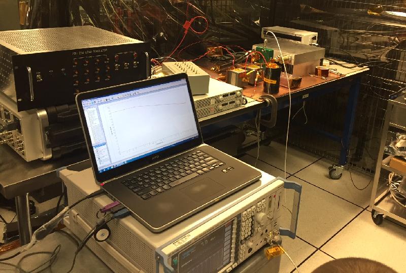
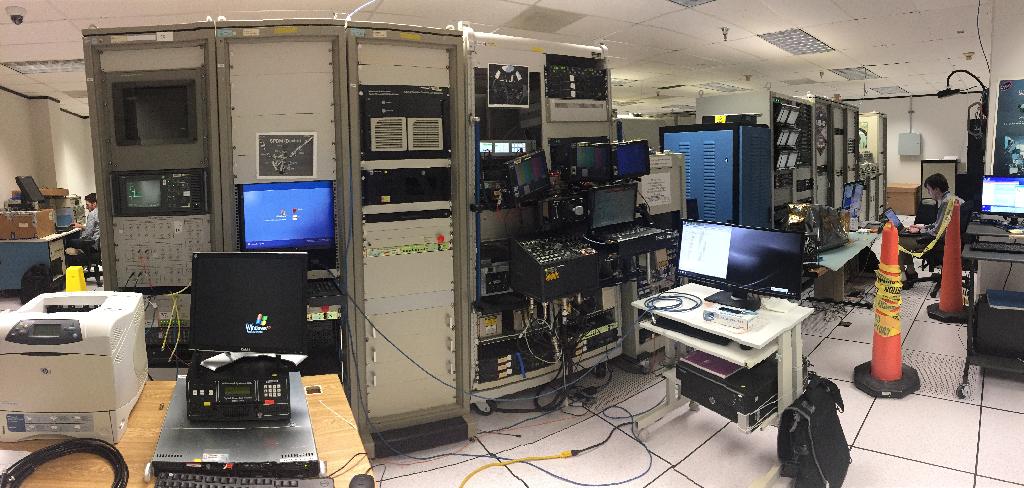
The first Engineering Development Unit to be tested was the Power Distribution Unit, which generates our low voltage power and has the switching MOSFETs to the many loads.
Here it is in our "Flatsat" lab being tested with EMI test equipment.
It is the Aluminum box to the far right.
(December 2016).

As part of the planning for our mission, we had a meeting with
SpaceX at the Hawthorne, CA factory. May 2017
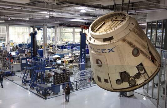
Picture from the web with a view from the cafeteria into the factory.
In the foreground is the first returned Dragon capsule.

In June 2017, we had a TIM with SpaceX at the KSC
launch site. This is inside the vertical processing
facility.

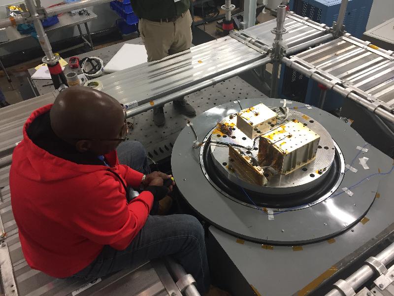
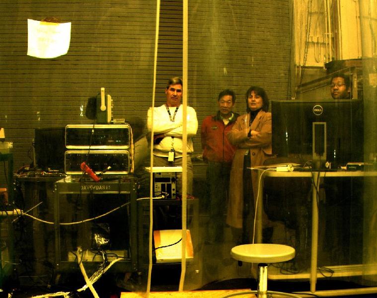
In June 2017, we had our first thermal vacuum test of RRM3, and it was a test to
see how the two cryogenic coolers would work in the RRM3 thermal environment.

View of the two coolers inside the vacuum chamber (June 2017). In RRM3, there is one
cooler for the Dewar that holds the Methane, and another for the Dewar that will
receive the Methane. With the latter, we can demonstrate a transfer and fill
without loss of cryogen.
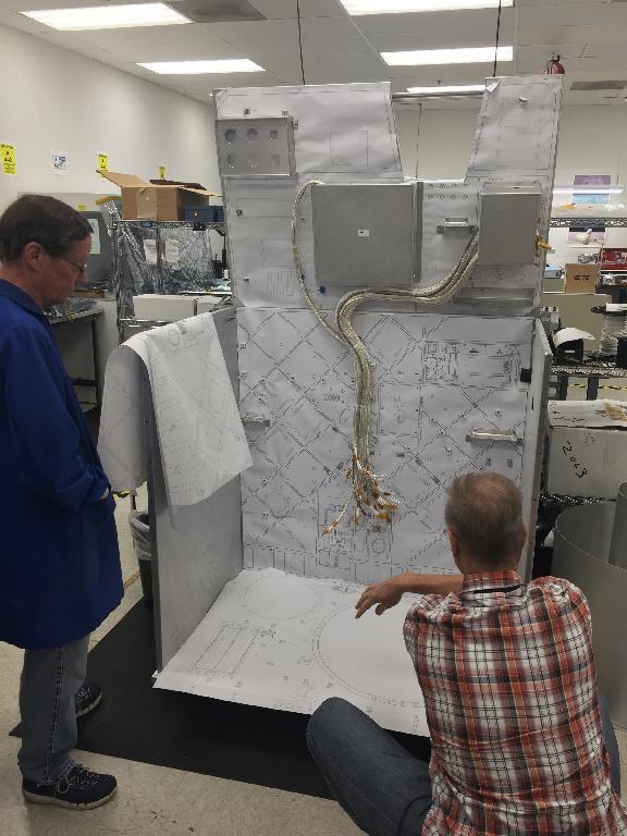
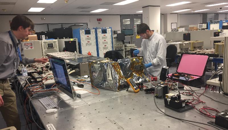
The wiring harness of RRM3 is extremely complicated compared to the previous ones
we built, so we built a mockup of the structure to use as a template to build the flight
harnessing (July 2017).

The wiring mockup gives a sense for the size of RRM3. It is a little
larger than RRM1, larger than a clothes washing machine.

As part of this project, we travelled many times to Los Angeles to meet at Motiv
Space Systems, where one assembly was being built. This electronics assembly
powers the twin cryocoolers and the various motors. (August 2017).

This image shot during a visit to MSS where we were able to show a successful run
with the cryocooler. This was a very important milestone in our development.
You can see the resonator on the left vibrating (August 2017). Snow
would form on the right end as it cooled down.
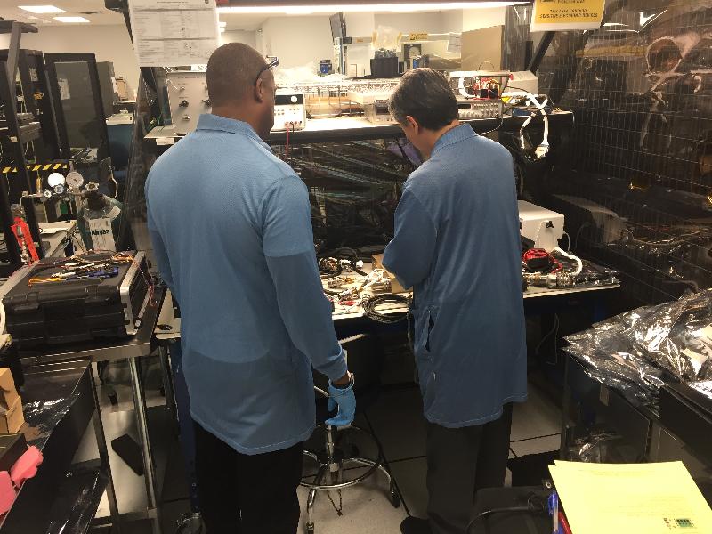
Around the same time back home, my colleagues were building the various
avionics units needed for RRM3. This is the Power Distribution Unit
on the test bench.
Here are other avionics units such as the SpaceCube being vibration tested
(November 2017).

We spent the month of December and January integrating half a dozen avionics units,
50 or so harnesses and numerous other smaller items together. Due to the complexity
and number of new technologies integrated there were many problems and
I would have a hard time sleeping. So sometimes I would nap in between
tests.

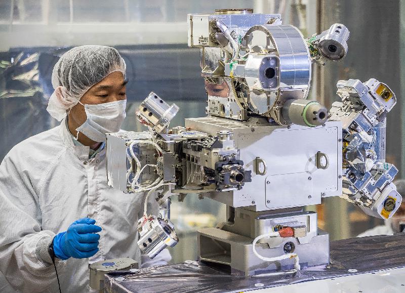
RRM3 does not consist only of the main Fluid Transfer Module, but also includes three
new robotic tools such as this one, the Cryo Servicing Tool (CST). This is it
undergoing EMI testing (December 2017).
To best ensure that the tools were compatible to the Space Station avionics system,
we would test with this facility at the Johnson Space Center (near the
Sonny Carter Training Facility). This is known as the SDIL. We would test
by connecting our hardware to this and flowing video and data (Jan 2018).
Something new for us is the Power Quality testing at the Power Lab at SDIL. In this facility, they subject our hardware to all kinds of power line anomalies to
verify we can handle the transients on the power bus on ISS (Jan 2018).
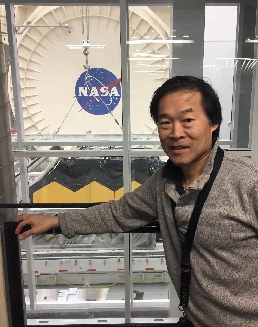
At one of these visits to the Johnson Space Center, I had the
good fortune of seeing the James Webb Space Telescope being
prepared for shipment to California after it had completed
its thermal vacuum testing (Jan 2018).
One of the first test images of the color pan-tilt camera.
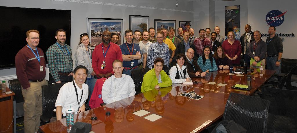
Team picture at the meeting where we were told we were GO for launch on SpaceX-16 (CRS-16). Feb 2018.
In March 2018 we did our final vibration test. This video is of the RRM3 being
craned into the vibe cell.

In February 2018, we loaded the RRM3 Fluid Transfer Module (FTM) into this large blue
thermal-vacuum chamber for round the clock testing against the rigors of space flight.
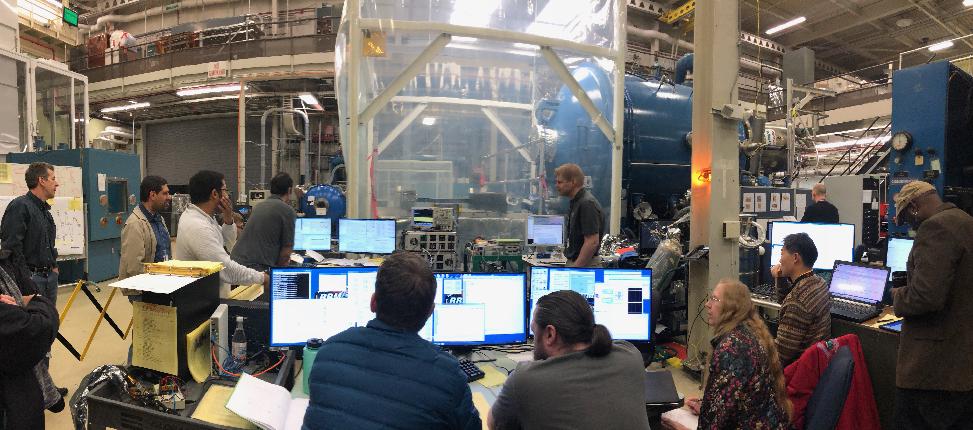
Shifts were 24 hours a
day and was done by a large team.
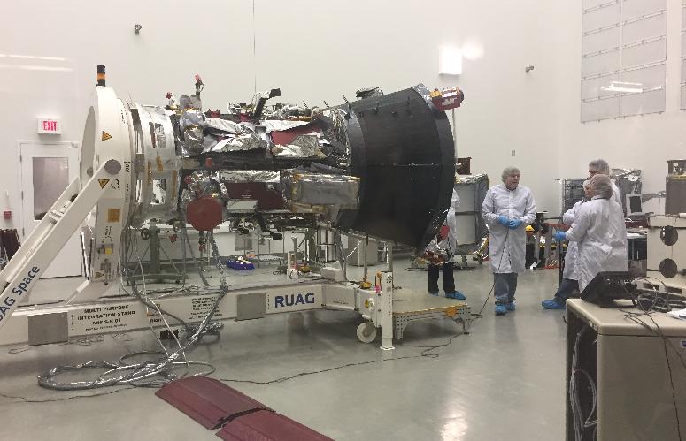
Around the same time as our tests in March 2018, the Parker Solar Probe was being
tested in our building.
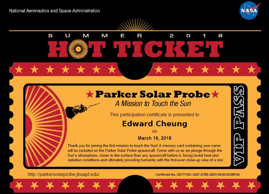 You could get a ticket
to ride to the Sun by registering on their web site.
You could get a ticket
to ride to the Sun by registering on their web site.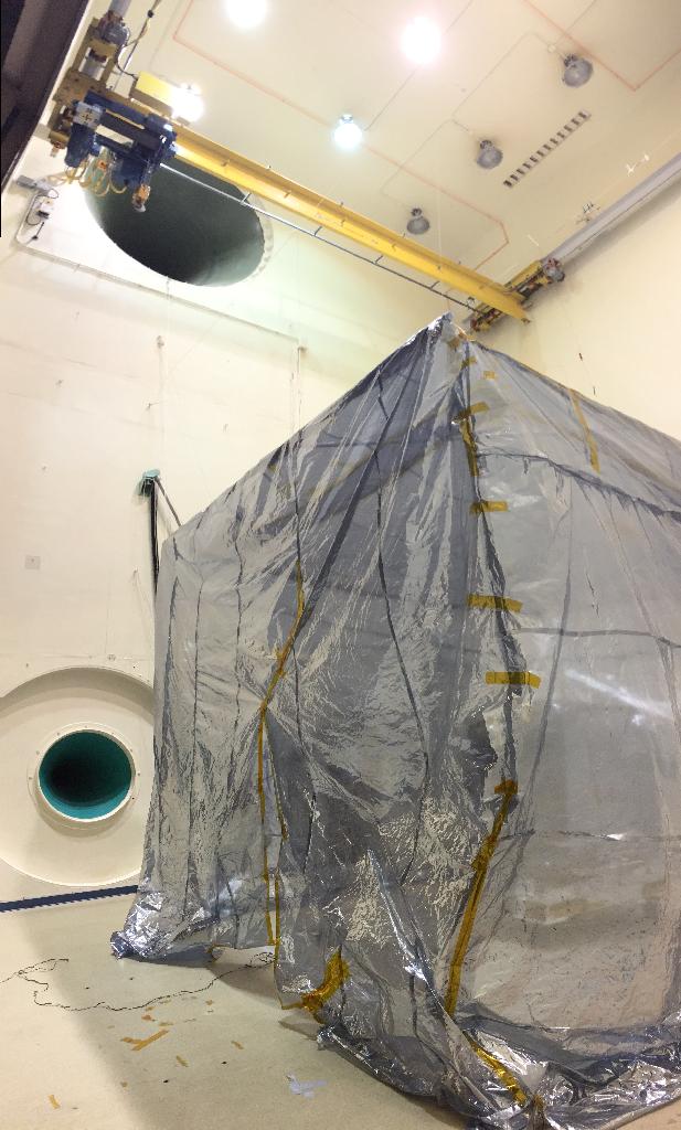
After Thermal-Vacuum testing, we did the Acoustic test. This is where
we place the hardware into a large room with two huge speakers
(on the left) that flood the room with sound to simulate
the rocket motors.
A picture for the scale of these horn speakers in the acoustic test cell.
Time-lapse video on the Goddard Facebook page during our
integration. I appear at the end on the right-hand side.
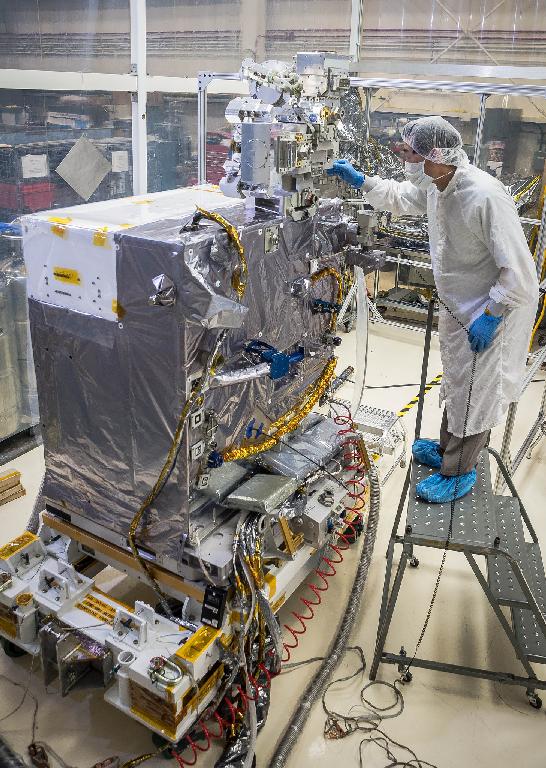
Here I am inspecting the three tools that will be placed on top of RRM3 by the
Space Station robot. (Officially released photos from April 2018).
Story on spaceflightnow.com with my picture.
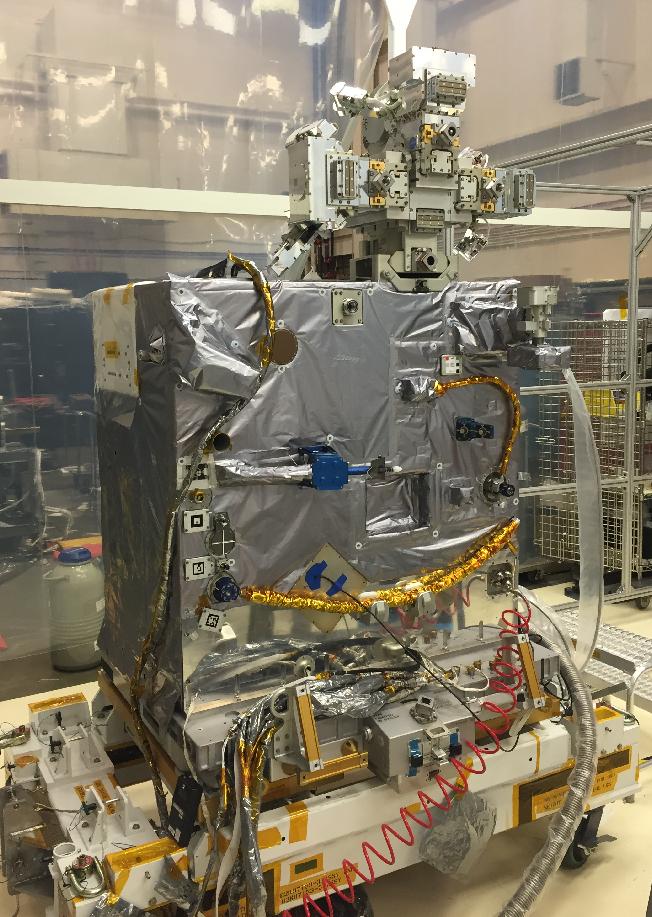
The complete RRM3 just prior to shipping to the Kennedy Space Center.
The cross shaped item at the top is the Tool Pedestal with its three
tools (MFT2, VIPIR2 and CST). These are joined with the main
FTM part in space, so this would be the only time they can
be photographed together (Officially released photo from April 2018).
Shipping to the Cape
After many years of work we finally ship to the Cape on May 7, 2018.

Truck used to ship RRM3 in the background. A large 50 foot long truck that was perhaps
half full with RRM3 and its mechanical and electrical support equipment (May 2018).

The leads do a signoff that we are ready to ship to the Cape.

Arrival at the loading dock of the Space Station Processing Facility (SSPF) in May 2018.

To verify we are compatible with the Space Station electronics, we perform a test with
the PRCU test system in the SSPF.

Just like with RRM1, I am the one that is slim enough to fit under
the wheeled stand in order to connect to the blind mate connector that
is under the RRM3 FTM.
In the PRCU test, my colleagues from Goddard control the RRM3 just like it
is in space through the NASA communications network. This is the best
test we have that the entire electronic and data system is compatible.

While at KSC, we take the time to tour the hidden historical areas of
the Space Center such as this Mercury 7 memorial.

The entrance and much of the old Block House (B/H) is restored
from the original Mercury Launch pad.
I also take the time to visit the Atlantis display at the KSC visitor's center.
Well worth the visit to see the Shuttle. I can remember all the times
I was inside her crew cabin. What a privilege.
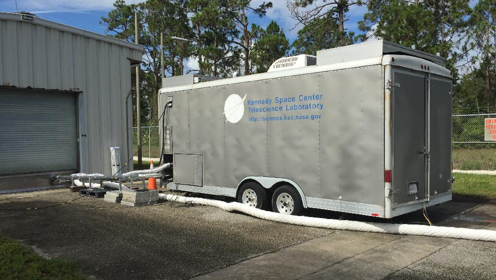
After our tests at the
SSPF, it is time to finally get down to the real business
of testing with Methane gas. This flamable commodity is not allowed at Goddard,
so we can only test here at the Kennedy Space Center. The FTM is
housed in the building on the left (called the FTB), and we have a metal conduit to
the command trailer in the middle of the image. From this trailer we can control
the RRM3 FTM to perform the internal Methane transfers.

Inside the FTB where the RRM3 FTM is housed. The tent around the
FTM is purged with clean air and inside of that we purged with
clean Nitrogen gas to prevent the Methane from mixing with oxygen.
(May 2018).
of testing with Methane gas. This flamable commodity is not allowed at Goddard,
so we can only test here at the Kennedy Space Center. The FTM is
housed in the building on the left (called the FTB), and we have a metal conduit to
the command trailer in the middle of the image. From this trailer we can control
the RRM3 FTM to perform the internal Methane transfers.
Inside the FTB where the RRM3 FTM is housed. The tent around the
FTM is purged with clean air and inside of that we purged with
clean Nitrogen gas to prevent the Methane from mixing with oxygen.
(May 2018).
The presence of Methane in our payload complicates the operation of the system on the ground. We fall under the Class 1 Division 2 rules (aka C1D2), and that means that no conventional electronics can be operating within 15 feet of the building that houses the system. This is why in our case we moved our operations computers to a trailer that is outside the FTB (with the cables held in a metal sealed conduit to keep out weather). In addition, for the flight electronics inside the RRM3, we continuously purge the contents with clean gaseous Nitrogen. The Lower Explosive Limit (LEL) of Methane is around 5-15%, so we need to push enough Nitrogen through the RRM3 to ensure that we do not come close to that even in the case of a leak.
In addition to that, we placed an enclosure around the RRM3 and that is in turn purged with clean (HEPA filtered) and air conditioned air to reduce the chance of build up of gas. It is also to create a mini-cleanroom around RRM3 to keep the flight hardware clean and free of humidity buildup. That enclosure can be seen in the image above.
These initial tests in May 2018 were very important as we had not used Methane before in RRM3. Prior to this, we had used Liquid Argon and Nitrogen for various tests. These tests were very useful for us to learn how to use the system. Once they were completed, we then moved back to the SSPF for summer storage. Due to us being moved to CRS-16 (SpaceX-16), we had time in our schedule for some down time.