| Home | Job | Pinball | Photo Album | Automotive | Press/Awards | Contact |

Satellite Servicing Demonstration
The Hubble Servicing Project goes to workon other Satellites
(Page 7)
Page 6 is here.
Continued On-Orbit Ops (Gas Valve
Panel)
In March 2012, we started our first significant operations in space by checking out the tools and their cameras as well as releasing launch locks and cutting wire. The long wait since launch was to load in the new software and scripts into the Space Station computer to be able to manipulate our hardware.
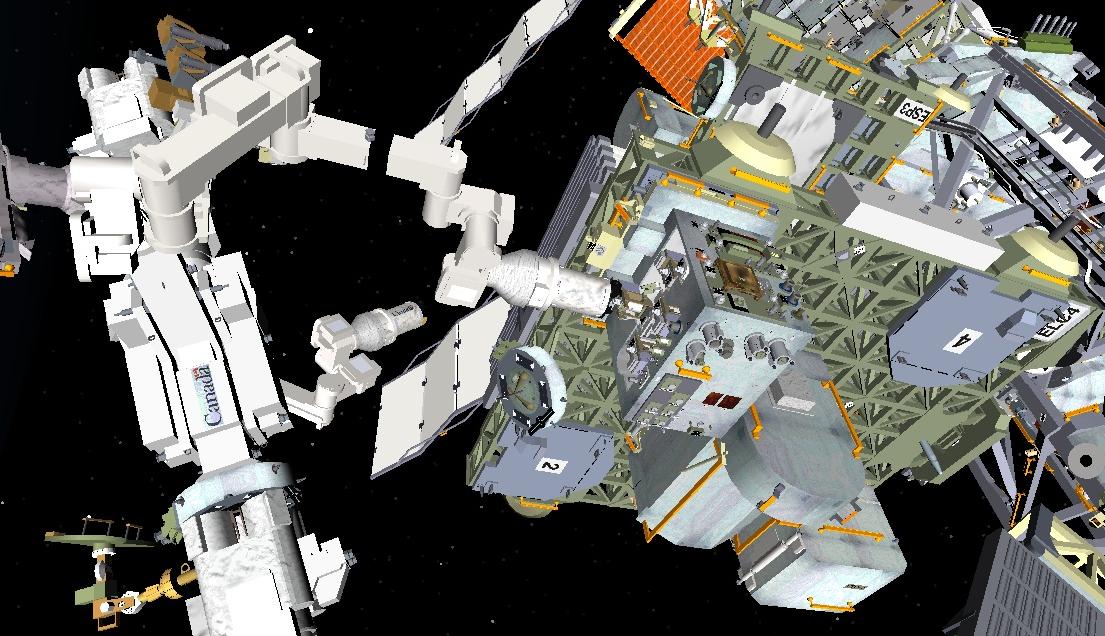
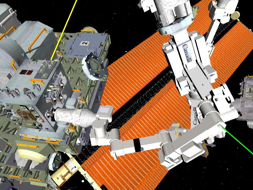
The overall layout of the Dextre robot facing our hardware. Our RRM module
is located on the ELC-4 exterior platform.

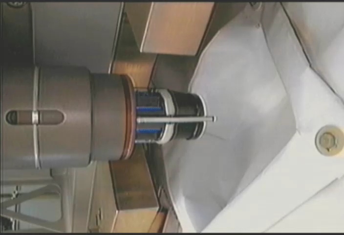
Photo of Dextre's end-effector (OTCM) approaching one of the tools,
ready to grasp and power it up.
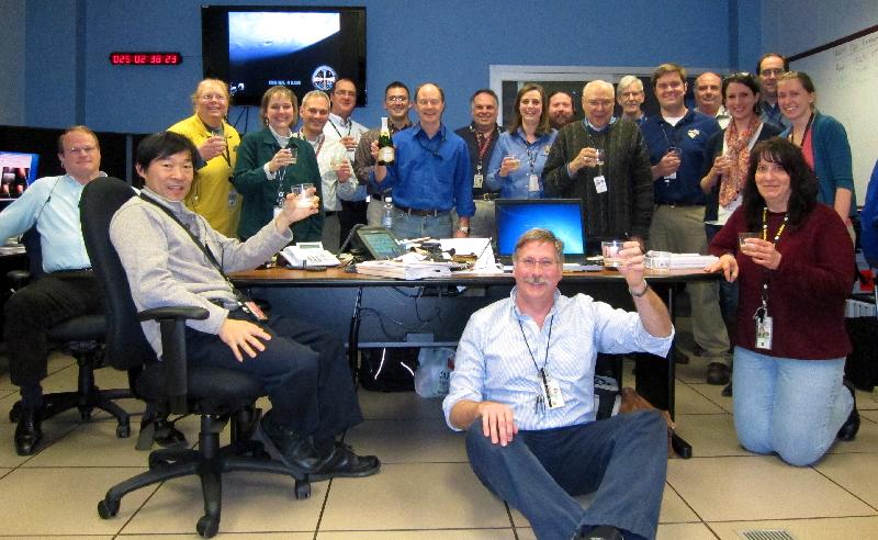
This is the first image from the tool cameras that we saw. There was a big
celebration of this success.
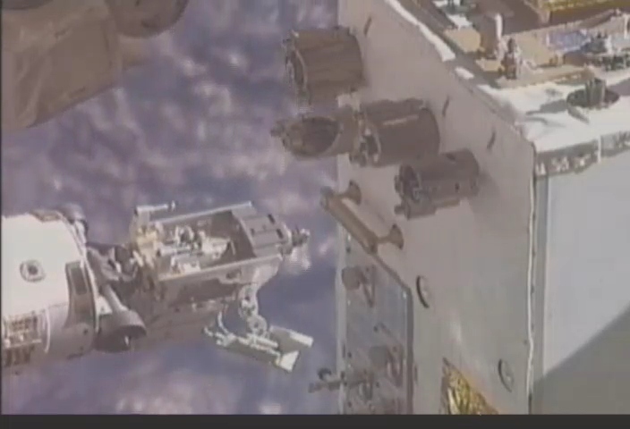
Once the tool was retrieved, Dextre is ready to go to work.
This is the Multi-Function Tool that will be used to
release the launch locks from the various parts.

Shot of us in the 'front row' of the GSSCC control center.

Mike Oetken (mechanical lead) showing the proper use of the Project Manager
console: getting us lunch and dinner 8-).

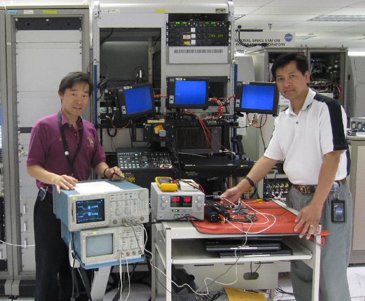
While we work in the control center, other staff work in our robotics lab
in case of problems encountered in space.
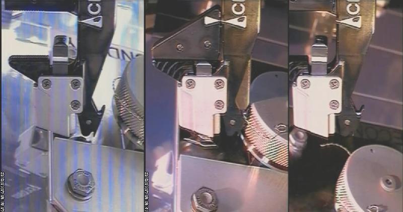
Sequence of images from the cutting of the wire on the Ambient Cap.
left: approaching the wire. middle: about to cut the wire, right: wire is cut.

To celebrate the successful on-orbit ops, we had a cookout one day, and
the chef was Ray Bietry (electrical systems).
In March 2012, we started our first significant operations in space by checking out the tools and their cameras as well as releasing launch locks and cutting wire. The long wait since launch was to load in the new software and scripts into the Space Station computer to be able to manipulate our hardware.
The overall layout of the Dextre robot facing our hardware. Our RRM module
is located on the ELC-4 exterior platform.
Photo of Dextre's end-effector (OTCM) approaching one of the tools,
ready to grasp and power it up.
The
tool cameras have been a special worry of mine since I designed their
interface circuitry in 2010. The Dextre robot video input is
required for the sync to be clamped to zero volts, while normal cameras
have a capacitive coupled output. This makes the two
incompatible. In addition, I was unable to allocate much
space to
any circuitry to fix this problem since it had to fit into the tool.
The circuit I came up with is very compact, and worked well
for
all the tests on the ground and at the ISIL
facility at the Johnson Space Center.
However, this was at only two separate occasions, all of our
tests on the ground were by commercial monitors, which is not similar
to the Dextre circuits.
In addition, we are the first users of the Dextre OTCM video inputs since it was launched, and no post-launch test was performed on this hardware.
So when the day, hour and minute came for the cameras to be powered on, I was quite nervous about what we might see. When the image below popped up, there was a big cheer at our control center. We were all relieved as without cameras, our mission would not be possible.
This is the first image from the tool cameras that we saw. There was a big
celebration of this success.
The
other unusual aspect of the two tool cameras is how we select which one
to send to the ground. Dextre OTCM input can only accept one
input, and I decided to not use the more complex 1553 computer
interface to select the camera. Instead, I designed a
magnetic
latching circuit that toggles between the cameras on each power cycle
to the tool.
Once the tool was retrieved, Dextre is ready to go to work.
This is the Multi-Function Tool that will be used to
release the launch locks from the various parts.
The
first task to be done was to release the launch locks. These
mechanisms lock down the movable parts of the system so that they do
not get loose during the violent shaking of the Shuttle launch.
We use the bolt driver in the Multi Function Tool for that.
Shot of us in the 'front row' of the GSSCC control center.
Mike Oetken (mechanical lead) showing the proper use of the Project Manager
console: getting us lunch and dinner 8-).
While
we follow the space robot in our control room, we also have staff in
our robotics lab following along with a ground duplicate of RRM.
They can then try solutions with the ground robot to give the
operators at the Johnson Space Center ideas and things to try.
In the image below, the top left screen is the graphical simulator that shows an overall view of the robot and Space Station. The next four on the far wall show the four video feeds from station. There are two ops stations in the middle of the room, the one facing away is for the robot operator (Joe Easley in the blue shirt). He is facing many of the same screens we see in our control room. Sitting to his back is the lead tools expert on console. On the far right, you can see the robot, and not seen is the RRM simulator we brought to the Kennedy Space Center for the press events. It is an accurate duplicate of the one in space.
In the image below, the top left screen is the graphical simulator that shows an overall view of the robot and Space Station. The next four on the far wall show the four video feeds from station. There are two ops stations in the middle of the room, the one facing away is for the robot operator (Joe Easley in the blue shirt). He is facing many of the same screens we see in our control room. Sitting to his back is the lead tools expert on console. On the far right, you can see the robot, and not seen is the RRM simulator we brought to the Kennedy Space Center for the press events. It is an accurate duplicate of the one in space.
While we work in the control center, other staff work in our robotics lab
in case of problems encountered in space.
Finally
after years of waiting, and days of tool checkout and launch lock
release, we finally got down to the first 'real' task. This
is to
cut wire. This wire is commonly used to tie down and lock
down
rotating caps and bolts so that they do not vibrate loose.
To perform these operations, the tool is on the end of Dextre, whose arms are about 11 feet in length. This in turn is on the SSRMS, which is about 60 foot long, and then mounted on the long Space Station truss. It was not known if this long path would lead to too much inaccuracy and floppiness to perform intricate tasks such as cutting wire. Prior to our mission, some thought it could not be done.
It turned out that it was not a problem, and we were able to cut two instances of wire very successfully.
Sequence of images from the cutting of the wire on the Ambient Cap.
left: approaching the wire. middle: about to cut the wire, right: wire is cut.
To celebrate the successful on-orbit ops, we had a cookout one day, and
the chef was Ray Bietry (electrical systems).
Article on this activity from nasaspaceflight.com.
Press release by Ecliptic, who furnished the
core of the tool cameras.
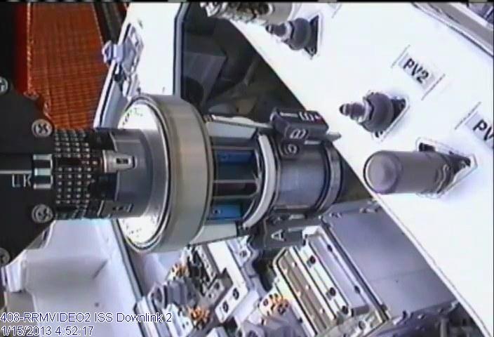
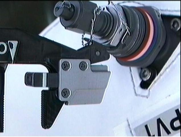
On
June 20 2012, we had our second round of operations and the conclusion
of the Coolant Valve Panel work started in March. In the
image
below, you see the Multi-Function Tool (ends at the black part with the
small white dots) holding the T-Valve Adapter (TVA). This in
turn
holds a T-Valve (aluminum block shaped object with tubes coming out and
the green ring). The valve was previously successfully
removed
from the task board that sits on the 'top' of RRM.
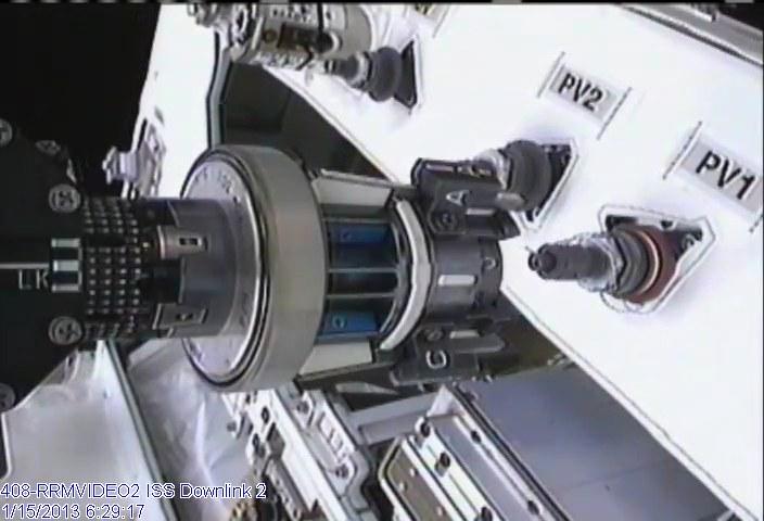
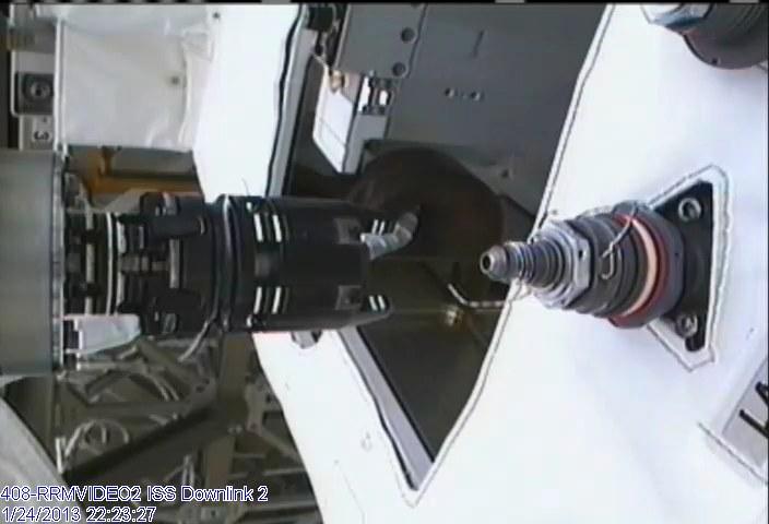
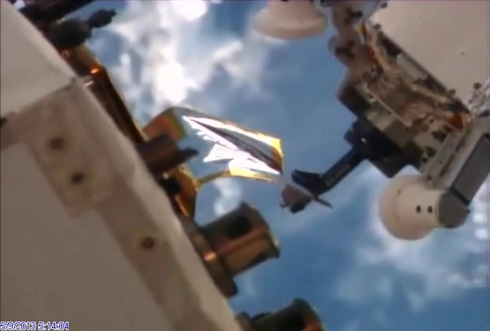
In the image below, we are translating over to stow the TVA, and the amazing sight is to see the T-Valve gently loosely bobbing around. It is mesmerizing to see it loose and with the Earth going by in the background.
In the image below, we are translating over to stow the TVA, and the amazing sight is to see the T-Valve gently loosely bobbing around. It is mesmerizing to see it loose and with the Earth going by in the background.

T-Valve removal in space. Note the Earth and the Station Solar Array below.
NASA.gov article on this second activity.
After years of preparation, we finally performed the main event which are the refueling tasks over the course of six days in January 2013.

Image of the Wire Cutter Tool (WCT) about to cut the wire on the
Tertiary Cap (visible in the top part of the image).
Once the wire is cut, we approach with the adapter to remove the Tertiary Cap.
Picture after. The Safety Cap is now exposed.
The next step is to now cut the two wires exposed. One holds the
Safety Cap closed, and the second is for the Actuation
Nut. This latter is the 'handle' of the refueling valve.
Close-up of cutting the wire on the Safety Cap.
We now finally have the EVR Nozzle Tool, which has the fuel hose, about to
be mated onto the fuel valve. All preparations are finally in place to refuel.
Refueling ends with this scene, the removal of the nozzle tool from the
refueling valve. What resulted was the most amazing sight of this mission.
Although we expected some small amount of alcohol release, I was very
surprised by how the release occurred. It came as a splash, and then the
alcohol lingered longer in vacuum than I expected.
The team in the control room for the main refueling task.
Spaceflightnow.com article
NASA Links:
Video
(Very brief cameo at 5:20)
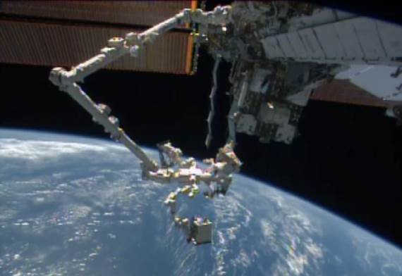
We use several cameras on Space Station but also have this CG tool (called "Doug") that we can create any virtual view we want. On the left you see RRM with its tools, and on the right you see Dextre about to grap the Wire Cutter Tool (WCT).
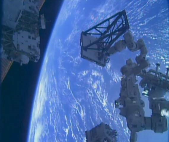
Picture to culminate Tertiary tasks. You can see the 65 foot long SSRMS, holding the 15' Dextre, holding our robotic tools, peeling open the demo flap of Multi-Layer Insulation (MLI). Pretty cool picture in my opinion.

In Spring 2016, the IMAX project released a preview of their movie "A Beautiful Planet"
About 30 seconds into this preview, you can see RRM in the right of the image.
(left most of the three rectangles in the right).
On March 5 2017 RRM was removed from its perch viewing the Earth after six years in space. It burned up along with the CRS-X capsule later that month (RRM is bottom most box in the image). You can see that ELC-4 payload Site 3 is empty.
SAGE III (frame shaped object was installed into the location formerly occupied by RRM.
The latter is just half in frame at the bottom of the image.
The original RRM mission ended in March 2017, but it continues with RRM3 (future blog).
In addition, work on satellite servicing continues on the Flex Hose Investigation page.
(includes my flight on the Zero Gravity plane).
Links
- March 2010 - MSNBC
article on satellite repair.
- August 2010 - First step to STS-135 approval, and mention of our project (called R2D2 at the time) in the press.
- December 2010 - NASA proceeding with STS-135 despite budget uncertainty.
- January 2011 - NASA officially declares STS-135 a real mission.
- January 2011 - In the news with STS-135 as "The mission also will fly a system to investigate the potential for robotically refueling existing spacecraft".
- February 2011 - Congress has not yet approved a budget, and NASA (along with other agencies) is operating under a Continuing Resolution. This is set to expire in a few weeks. Unless the next CR is cut, there should be enough funding for STS-135, which is the flight we will be using to take RRM into space.
- February 2011 - Another mention of us in the news, alluding to our problem in the thermal-vacuum chamber. I am glad we overcame those problems.
- April 2011 - The Wikipedia page on STS-135 links to this one.
- April 9 2011 - Space.com
article on RRM.
- May 23 2011 - Spacenews.com
article on my boss, Frank Cepollina.
- June 6 2011 - Official SSCO web site goes live.
- June 13 2011 - Updated
Space.com article on RRM.
- June 14 2011 - NASASpaceFlight.com article on future ISS uses, including RRM.
- June 16 2011 - Popsci article on Dextre.
- June 19 2011 - Much to our chagrin, Commander Ferguson refers to us as "Fisher-Price play toy" 8-).
- June 21 2011 - Announcement by MDA on their ongoing efforts with servicing Intelsat. Press release. MDA is the Canadian company that built the robot arms on Station and Shuttle.
- June 21 2011 - Article on the potential effects of NASA's satellite servicing efforts on MDA.
- June 23 2011 - NASA explains role of RRM and future sat servicing work.
- July 6 2011 - Very detailed article on RRM.
- July 6 2011 - Russian space agency to get into satellite servicing.
- July 8 2011 - Washington DC affiliate program on our launch.
- July 12 2011 - Story
about father and son witnessing the first and last launch
together.
- July 15 2011 - President mentions us in his call to the astronaut crew.
- September 2011 - We are mentioned in the inaugural issue of Space Quarterly.
- March 2012 - Coverage of the first part of our on-orbit operations: wire cutting and first part of coolant valve panel.
- June 22 2012 - Second part of coolant valve panel operations in space. NASA.gov.