| Home | Job | Pinball | Photo Album | Automotive | Press/Awards | Contact |

The Diode Box Controller (continued)
On Orbit
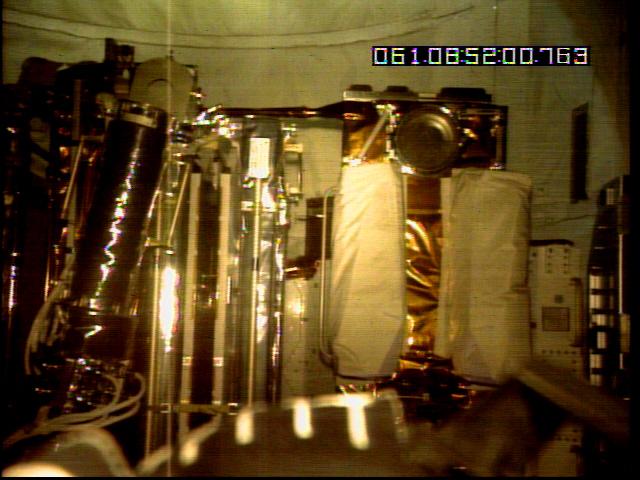
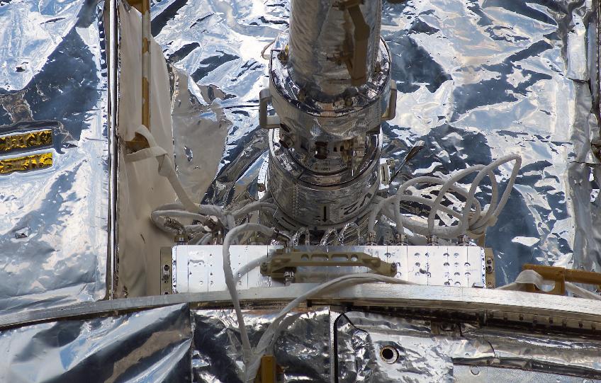
Here are two of the three Diode Boxes on the RAC (Rigid Array Carrier)
during the photo survey after
launch. The two white boxes cover them for thermal
protection.
Above the boxes, one can see the round
clamp ring for the old flexible solar arrays. A ring such as
this one fastens them to HST. The part on the
bottom of the image is the end of the robot arm. The
end-effector
camera was used for this image.

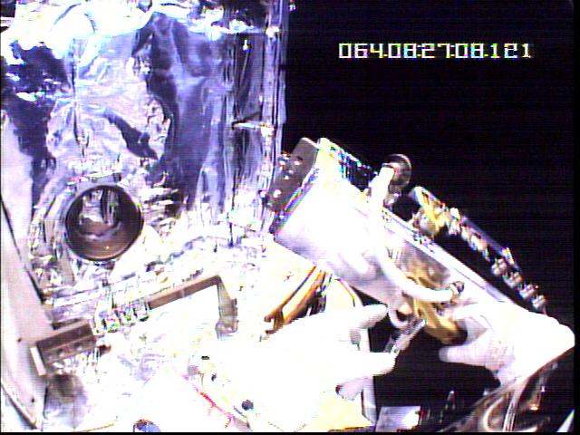
Installation of the first Diode Box during EVA1 on Flight Day
4.
Taken with the helmet
camera of the astronaut.

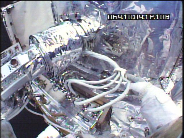
A wider shot including the mast of the solar array just above the Diode
Box.
Installation of the second Diode Box during EVA2. On the
left,
one can see the tray into which it will be placed,
and above that, the circular clamp ring where the Solar Array will
be installed.
Installation of Diode Box and Solar Array complete.
Final view of the installed Diode Box.
The display of the CCS system after the successful functional test
of the Solar Array, which includes
the activation of the Diode Box by the Diode Box Controller.
The DBC's circuit takes commands
from the HST computer, and activates relays open and close, changing
the charging of the batteries.
The top trace shows the power into the 7 sections. The first
rising edge is the closing of the PCU Trim relays,
the first falling edge is the opening of the Disconnect Relays, the
next rising edge is the closing of the Disconnects,
then the stairsteps down is the opening of the Charge Control Relays,
one-by-one. The next rising edge is the
closing of the Bypass Relays, after that the falling edge denotes the
opening of the Bypass. Finally, the last
pulse of current is the closing of the charge control relays.
I was cheering with every blip on this trace.
Conclusion
We look forward to many years of service from this vital spacecraft system.
The journey to build the DBC started in May, 2000, and has ended with its installation onto HST in March 2002.
It has been an educational and fun experience.