| Home | Job | Pinball | Photo Album | Automotive | Press/Awards | Contact |

Weather Node

(funnel) has since moved to here.
One of the nodes on the home control network is my weather
node. The
system tracks 8 parameters. They are : wind speed, wind direction, rain
fall, outside temp, outside humidity, inside temp, inside humidity, and
barometric pressure. I then derive three additional parameters, which
are
: wind gust (max winds over a period of time), the outside dew point,
and
the rain fall rate.
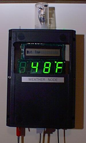
The weather node
The weather node is shown above. It has an LCD display with the name of the parameter
shown on the LED display. Currently, the outside temperature is shown.
At the top left is the switch to change the parameter shown, the middle
top has the inside temp and humidity sensor. On the bottom left (red
plug)
is the power cord, the middle bottom is the Home Automation Network
connection, and the bottom right is the fiber optic connection to the
sensor pod on the roof.
The external parameters are collected by an 18 pin PIC inside
the
weather
instrument on the roof. The data is relayed via wire and fiber optic
connection
(the latter for lightning protection) to my inside node which displays
one of the above parameters on a four digit 7-segment display and a 16
character LCD panel. The inside PIC also handles communication to my
HCSII
conformant network to allow the home control computer access to this
data.
If you wish to build part of the system, here is how I would
suggest
you go about it:
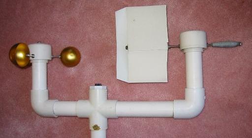
Anemometer and Wind Vane
The design of both these items is from the Electronics Now, Oct. 93
article
by Fascinating
Electronics
(FE). They are made from commonly available items such as
Schedule
40 PVC tubing. I purchased some hard to find parts from FE, but 90% of
the items were bought at my local home center (Lowe's).
I made two small changes to the anemometer, I used a Hall effect sensor
instead of the magnetic switch, and I used a 1/4" bolt instead of the
#8
bolt as the main axle. I also used 1.25" pipe instead of the 1.5" pipe
throughout, and added a lightning arrestor to the top of the whole
thing.
I estimate the output of the anemometer to be approximately 0.476
revs/sec
per mile an hour of wind. The friction is low enough that it start
rotating
at 1-2 mph.
Rain fall gauge
The design is similar to the EN article, except I adapted the whole
thing
to fit inside a 1.25" 'T'. This makes it much more compact, and allows
it to be fastened by suitable plumbing to the above two instruments on
the roof stalk. It has a resolution of 1/32" of rainfall, which is a
little
less sensitive than original sensor since I used a more compact
funnel--I
was afraid of saturations in heavy rain, and for cosmetic reasons.
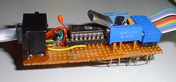
on the left leads to the optical link and power supply,
the ribbon cable on the right leads to the transducers.
Temp sensor
I decide using the plain old LM34 as the temp sensor. This outputs 10mV
/ F, and by setting the reference input on the A/D on my PIC to 2.55
Volts,
it allows me to directly read degrees F with no analog processing
circuitry.
I purchased the sensor from Digi-Key. By biasing the LM34
appropriately,
I can read temps down to -25F.
Humidity sensor
This is the moisture sensitive capacitor that detects humidity. I
purchased
this from Newark Electronics
for
about $9. The circuit I use is the
same
as in the EN article. My PIC counts the frequency directly, and results
in good accuracy since my only temperature sensitive components is the
humidity sensor and two 100ppm/C resistors (the chip oscillator has a
very
low temp sensitivity). Vishay Corp. part #2322-691-90001,
Newark
part
#89F5822.
[A
check
in Jan 2016 shows that this unit is discontinued. An
alternate source is Digi-key
part no BC1333-ND (courtesy
Steve Lapinskas)]
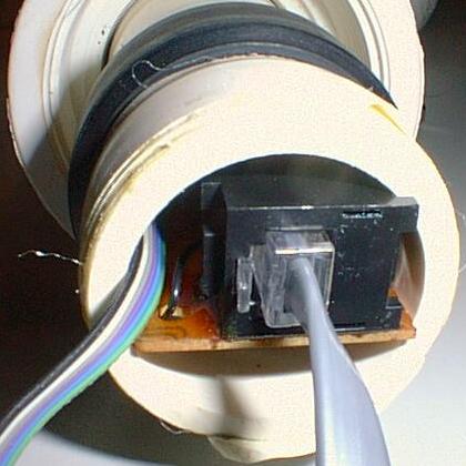
The micro installed into the tube of the weather sensor pod.
The result is a neat installation that is easily removable.
The result is a neat installation that is easily removable.
Barometric Pressure
This sensor is one of the Motorola absolute pressure sensors, also purchased from Newark. It comes with a small port so you can attach some tubing to it. With a gain of about 5 or 6 on the output, you can get 10mV/0.01" mercury. This should be plenty for weather prediction/ logging applications. The sensor is Motorola #MPX5100ASX and costs about $27.00. The sensor itself is made of a semiconductor, and has temp compensation and and instrumentation amp built right onto the same die.Fiber connection
The kit is sold by Digi-Key as an experimenter's kit. It includes fiber, one transmitter, and one receiver in the SMA style of fiber optic holder. Operation is rather simple. You forward bias the LED, and the optical transistor on the other end conducts. By suitable biasing one can use this to replace an EIA/RS232 line. Since air breaks down at about 3 megavolt/meter, this will afford me some protection against lightning.Conclusion
If you would like to build your own, I would suggest that you lookup
the
above mentioned article. It also contains the address of Fascinating
Electronics,
from whom you can buy the hard-to-find parts such as the bearings and
the
dual wiper pot for the wind vane.
In addition I would like to add that I appreciate all the
posts and
email that I received from my request for discussion. I think the most
important 'lesson' from all of it is to take lightning seriously.
Now the fun part of collecting and analyzing data begins. I
have
already
noticed a few well known correlations among the various data points: -
at night the temp falls, the reverse is true during the day
(surprise!).
- with no rainfall or strong wind, the falling temp at night is
accompanied
by rising humidity. - rapid changes in barometric pressure is
accompanied
by strong winds.
The local NBC
affiliate used to offer 24 hour history plots
of the parameters that I am measuring. When comparing the data, one is
struck by the similarity in their appearance.
Humidity chart at WRC4 for 3/26

Humidity chart from my weather station for 3/26
Related Links
Long term update
- March 11 1996. The weather station starts continuous operation.
- May 1997. After more than one year of operation all is working well. One minor glitch is that the rain fall sensor's sensitivity has dropped a little. However since the sensor is so high up, I won't be able to get to it easily, and I will have to live with it.
- December 1998. The weather station was removed from the roof for service during the fall of 1998. In general, the condition of the sensor pod was good, the following items needed to be fixed:
- The thin PVC parts were brittle and pitted. These included the anemometer cups and the rain funnel. These were replaced.
- The pot that registers the wind direction was damaged, probably by repeated movement of the wiper. I would say the pot has lasted 2 years.
- I found out why the rain sensor stopped working. After a while dirt accumulated and dried onto the rain sensing spoon. This added weight stopped it from tipping. The only good long term solution would be not to use a rain sensor at the top of the house, but near ground level where it can be easily cleaned.
- The initial installation and removal of the sensor pod required hiring someone to go up on the roof. This was undesirable to me. To address this I made a small vent window in the side of the house which I could reach by climbing on the trusses of the roof. In this manner, I could access the pod from relative safety from the attic of my home.
- March 1999. The anemometer stopped working. I was able to easily take the sensor pod down from the roof to find out why (thanks to the access window mentioned above). It turns out that the ball bearing that I used for the anemometer was damaged (after 3 years of operation) and needed to be replaced. This episode made me realize that I needed a spare ball bearing, and I was pleased to find out that Fascinating Electronics (FE) was still operating, and they are now web accessible. Since 1996, they have upgraded various parts of the weather sensor. In particular, the anemometer cups are deep drawn aluminum, and the wind vane is also aluminum. This new ensemble looks very nice, and I will probably upgrade parts of my system in the future. I ordered two wind vane wiper pots and two ball bearings.
- April 1999. The new ball bearings arrived, and I replaced the faulty unit.
- September 2001. Anemometer ball bearing gives out again, this time after two years. It is replaced with a spare unit. As preventative maintenance, I also replace the wind vane wiper pot. Four additional bearings and wiper pots are ordered. Over the past year, the outside temperature sensor inside the pod has become flaky, so I solder all the connections on the wire-wrap board to fix this.
- March 10 2002. The PVC anemometer cups degraded to the point that they flew off! I called Fascinating Electronics, and they have improved the overall unit again. This time, they added deep drawn aluminum cups that should last forever. In removing the unit from the roof I realized that its great weight was a big problem, and I modified the unit to make it lighter and easier to handle. I removed the lightning arrester and moved it down, and I removed the rain gauge. That latter part never worked right, as dirt would foul up the unit after a few months. I also shortened the stalk slightly. All these changes, made near the six year anniversary of the weatherstation, made the unit much easier and safer to handle.
New modified weather station pod. Lightning arrestor and rain
gauge removed.
- July 23 2003. After missing the rain gauge for more than a year, a new one has been built at ground level here.
- March 13 2004. Another service call to the roof:
- Replaced ball bearing in
wind
vane. This unit has lasted 8
years. I have a few of these bearings left.
- Replaced potentiometer in wind vane with a sealed unit from Fascinating Electronics (first time sealed type used).
- Soldered PIC into a socket and soldered all previously unsoldered wire-wrap connections due to temp sensor erratic going from max to min readings. It is clear that in outdoor environments, wire wrap construction will only last a few years.
- The humidity sensor has stopped working, but since I was unable to find the spare one in my parts bin, so it was not changed it out.
- October 30 2006. Roof pod stopped working.
- Replaced crystal because the leads broke due to corrosion.
- Resoldered in 10k pot (it got loose).
- Replaced humidity sensor.

Image of the sensor electronics taken in 2020. After almost 25 years on the roof
everything is quite corroded.
- June 2020. Total redesign of the roof sensor unit. After almost a quarter century in the elements, the electronics inside the roof sensor unit (so-called Weather Slave) have corroded and stopped working.
- I built a new electronics unit and moved its location into the attic so that it is less prone to corrosion. It can be operated either in the attic or sitting at the Weather Node for easy code development (using no additional wiring). Instead of using UV erasable device (PIC 16C71), it uses a Flash based 16F877. Much easier code development and In-Circuit Debugging is very handy. See image below
- Removed the wind vane and I decided to focus on digital only interfaces. Thus I eliminated the outdoor humidity (sensor would fail after a few years due to temperature swings), and also the wind vane (the dual potentiometers would fail due to the constant wiping back-and-forth). Also eliminated the roof temperature as it was of limited value.
- The only sensor remaining on the roof sensor is the anemometer, and it connects to the Weather Slave via a three-wire cable to drive the hall effect sensor in the cap of the spinning sensor. It is now also much lighter and safer to handle for me than the original design.
- This
weather slave now has its own 1-Wire network and collects temperature
data for the attic zone, and the heat pump air handler unit.
Initially this function was handled by the Thermostat Node,
but I found that running such a long 1-Wire network proved unreliable
(too much capacitance on the line). So I greatly reduced the
length of the network for the Thermostat Node and the temperatures for
the Heat Pump are now monitored by the Weather Slave. These
temperatures are the Intake, Exhaust and Attic Temperatures.

New version of the weather slave node electronics.