| Home | Job | Pinball | Photo Album | Automotive | Press/Awards | Contact |

Smoke Detector Interface
I have always wanted to
alert the
Home Automation System if the smoke detectors were triggered.
I
had previously thought of using a microphone near one of the units to
pick up the sound of the siren, but this seemed a little kludgy to
me. Alternately, I noticed that there is a third red wire
that
connects to each smoke detector. I have always wondered if
this
could be used to monitor any alarm conditions. However
considering that this is a system fed by 120V, I have always hesitated
to put test equipment onto that line. Then in the Spring
of 2004, one of our smoke
detectors started to chirp periodically. Unlike previous
times, a
new battery did not resolve the problem. Since I have heard
that
smoke detectors should be replaced
after 10 years, I decided to change them all as they are all
the
same age. After purchasing a new set of detectors, I noticed
an
interesting device on the "Interconnect Diagram" on the enclosed
instructions. It was an optional accessory called
the
"Lifesaver
Relay Module Model
120x".
The above diagram shows how
the system
is interconnected. Each smoke detector is supplied power from
the
120V power line via the Black and White wires. In addition,
there
is a Red wire in the system that connects only to the smoke detectors'
red wire. This is obviously the means by which they
communicate
with each other, and I decided to investigate the voltage on this line
during an alarm event.
As a start, I first pressed the 'test' button on the basement smoke detector (the most accessible unit), and was pleased to hear that the other smoke detectors in the home also sounded. This meant that I had a ready means of stimulating the interconnect feature. Using a DVM, I quickly found out that when there is an alarm event, 9 Vdc is present on the red wire with respect to the white 'neutral' wire. I could connect a relay to this red wire, and signal the Home Automation System. After some further readings, I put the results in a model of the interconnect output that is shown below:
As a start, I first pressed the 'test' button on the basement smoke detector (the most accessible unit), and was pleased to hear that the other smoke detectors in the home also sounded. This meant that I had a ready means of stimulating the interconnect feature. Using a DVM, I quickly found out that when there is an alarm event, 9 Vdc is present on the red wire with respect to the white 'neutral' wire. I could connect a relay to this red wire, and signal the Home Automation System. After some further readings, I put the results in a model of the interconnect output that is shown below:

SPICE model of the Kidde Smoke Alarm's Interconnect output. As one can see,
the open circuit voltage is 9V, and the output is limited in current. Each smoke
alarm's sensing circuitry has about 24 KOhms of input impedance.
Schematic of the smoke detector interface. By using an opto isolator, very little
current is drawn from the interconnect circuit.
An opto isolator essentially couples current from the LED circuit to
the transistor circuit by using an optical connection and the gain of
the transistor. You can speak of a Current Transfer Ratio in
the
opto isolator: the higher you drive the LED current, the more base
current is generated, and the more collector current you can have in
the output transistor. A CTR
of about 1 is considered a good rule-of-thumb. So
for every
mA that you drive the LED, you can estimate a collector current of 1mA.
With some experimentation, I found that the largest series resistor that I could use for the LED was about 1.6kOhms. I settled on the above values to ensure margin against excessive loading and proper turn-on of the LED (two resistors so that if one should short out, the other will limit the maximum load on the interconnect circuit). Since the maximum current in a sensing zone of my Security Node is 5mA, I could connect the output transistor directly to the zone's wires. Since only three parts are needed, I could mount the whole thing on a small perf board and housed it inside an empty medicine bottle.
With some experimentation, I found that the largest series resistor that I could use for the LED was about 1.6kOhms. I settled on the above values to ensure margin against excessive loading and proper turn-on of the LED (two resistors so that if one should short out, the other will limit the maximum load on the interconnect circuit). Since the maximum current in a sensing zone of my Security Node is 5mA, I could connect the output transistor directly to the zone's wires. Since only three parts are needed, I could mount the whole thing on a small perf board and housed it inside an empty medicine bottle.
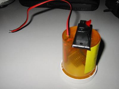
The finished interface module housed in an old prescription medicine bottle.
The two terminal speaker connection is for the transistor output, and
the pigtail leads connect to the smoke detector network.
Since I would be running a
long cable
from the
site of the smoke detector to the Security
Node,
I used a two terminal speaker connection block for the alarm
interface. This allows easy connection of the long cable, and
disconnection for troubleshooting. This cable was connected
to a
normally-open circuit on the Security System.

The relay module wired
into the
basement smoke detector. It is
placed
next to the ceiling junction box on the suspended ceiling. Note the Black,
White and Red wires from the smoke detector.
next to the ceiling junction box on the suspended ceiling. Note the Black,
White and Red wires from the smoke detector.
I reprogrammed the system
to incorporate
the new interface. Now if smoke is detected the Home Security
System will be triggered, and the system will send me a text
page. In the future, I may add additional smarts such as turn
off
the two HVAC systems etc.
Knowing the right time and temperature when cooking in your oven or
microwave should avoid your smoke alarms going off unnecessarily.
Baked potatoes can burn in the oven or microwave so check what
temp for baked potatoes with a cooking calculator.
Long
term update/Project Log
- April 2004 - New smoke detectors installed into home.
- 15 July 2004 - Smoke detector interface installed.
- 2013. New smoke detectors installed and they are still compatible with this relay module.
- June 2014 - Received a note from Anthon Pang that interconnected CO sensors use a pulsing signal on the common line to indicate alarm (vs steady signal from smoke sensors).
- June 2017. James Campbell's version of this project. Check it out.
- Jan 2018 - Ed Bade sent me the link to the Kidde SM120X page (added above).
Knowing the right time and temperature when cooking in your oven or
microwave should avoid your smoke alarms going off unnecessarily.
Baked potatoes can burn in the oven or microwave so check what
temp for baked potatoes with a cooking calculator.
Main Home Automation Web Page
(c) Edward Cheung, 2023