These were about $60 a pair with charger
and batteries, and have a three-bar battery gauge. With
experimentation I found that if the voltage is greater than 4.28V, all
three bars light up. More than 3.47V, two bars will light
up. Below this latter voltage the radio chirps regularly, and
only one bar will light up.
After a few years use, we noticed the batteries do not last longer than a few hours, so I wanted to replace them. A search on the web shows that the battery packs are about $12 each (plus shipping), and their capacity is still only 600mAh, so I decided to investigate a home-brew battery replacement for these units. I pealed back the sticker on one battery pack and discovered that the hidden elecronics are very simple and can be easily reproduced. One terminal of the charger connections connects to the negative terminal of the battery pack, and the other terminal connects to the positive terminal via a blocking diode.
After a few years use, we noticed the batteries do not last longer than a few hours, so I wanted to replace them. A search on the web shows that the battery packs are about $12 each (plus shipping), and their capacity is still only 600mAh, so I decided to investigate a home-brew battery replacement for these units. I pealed back the sticker on one battery pack and discovered that the hidden elecronics are very simple and can be easily reproduced. One terminal of the charger connections connects to the negative terminal of the battery pack, and the other terminal connects to the positive terminal via a blocking diode.

Photograph of the inside of the battery pack with the outer sticker removed. Notice
the small fuse (near the left side) and the diode (middle of picture). The part number
on the original pack is HKNN4002B.
These are the items you will need to do
this do-it-yourself replacement:
- Three AA rechargeable batteries (NiMH
or NiCad).
- Sticky Copper tape (3.25"x0.75" strip).
- Silicon Diode Rectifier (1N4001 or equivalent).
- One 8.5"x11" sheet of card stock paper. 110lb grade, although almost any grade of stiff paper will do.
- Begin by cutting a 1.5"x1.5" piece of the paper. This will
serve as your substrate.
- Cut the strip of sticky copper tape into three pieces. They are 1", 0.75" and 1.5" in length respectively (all 0.75" in width).
- Insert the three batteries into the radio, and verify that it
powers up. If it doesn't you may have to bend the metal tabs out
to meet the battery terminals.
- Take the 1.5" section of copper tape, and make a cut into it in
the middle of the long side. Cut only half way through the width.
- Remove the paper backing, on the tape, and fold the tab over so
that the tape forms a 'b' shape. The top arm of the 'b' is not
sticky on either side because you folded the tab over. The bottom
belly of the 'b' is sticky.
- Tape the bottom (belly) part of the 'b' onto a corner of the
paper substrate (top copper tab in the pictures below). Have the
non-sticky top arm stick out of the edge.
- Insert the top arm of the 'b' under the negative terminal of the battery. Since you folded the tab under, both sides of this leg are exposed copper and will make good contact with the battery and the radio terminal.
- Tape the 0.75" square piece of copper tape in the opposite corner of the paper (see below). The two previous squares now form the charging contacts for the new pack.
- Take the remaining copper strip and make a 'P' with it by cutting half way through the long side and folding it back.
- Insert the leg of this 'P' under the positive terminal of the right most battery (not sticky), and glue the exposed tape onto the paper substrate (bottom picture).
- Solder the diode to the latter two copper tabs. Cathode
ring toward the positive battery terminal as shown in the bottom
picture. Put the diode in the crease formed by the gap between
the two batteries.
- Snap cover back on and test in charging stand. You may need
to bend out the contacts in the cover to touch the two copper tabs on
the paper substrate.

Half way through the battery replacement. note that one of the copper strips
is been inserted between the negative terminal of the left most battery. The
unit is now ready for the installation of the diode.

Picture of the completed replacement. After this, you just snap the cover back on
and test the radio in the charger.
The original battery packs are only
600mAh units. The new ones are more than three times the capacity
(I used NiMH), and should last us a few days between recharging with
even daily use. Remember to recycle your used batteries as they
contain Cadmium.
After some use it became clear that the circuitry in the charger needed to be modified to provide more charge current for the batteries. Tracing the circuit, I came up with this schematic.

Circuit diagram of the charger. Each radio is charged on a different half cycle of the AC waveform.
To increase the charging current, I shorted R3 and R6 with a jumper and
replaced R2 and R5 with a 10 Ohm resistor. This quadruples the
charging current from the standard 39mA to 155mA (both measured).
It is still below the C/10 slow
charge rate, so it should be safe to leave the radios charging for
extended periods.
On a somewhat related note, I tend to collect somewhat unusual wrist watches, so I decided to buy this pair of radios on ebay for $25.
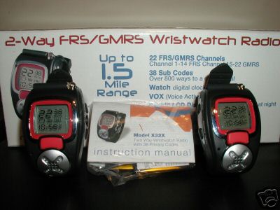
Cool Dick Tracy wrist watch radios that I bought on ebay. They have
FRS/GMRS channels with privacy code. The latter feature is
unusual among wrist watch FRS radios.
After some use it became clear that the circuitry in the charger needed to be modified to provide more charge current for the batteries. Tracing the circuit, I came up with this schematic.
Circuit diagram of the charger. Each radio is charged on a different half cycle of the AC waveform.
On a somewhat related note, I tend to collect somewhat unusual wrist watches, so I decided to buy this pair of radios on ebay for $25.
Cool Dick Tracy wrist watch radios that I bought on ebay. They have
FRS/GMRS channels with privacy code. The latter feature is
unusual among wrist watch FRS radios.