| Home | Job | Pinball | Photo Album | Automotive | Press/Awards | Contact |

Sharper Image LM521 Atomic Projection Clock
Transmitter Repair and Deconstruction
My clock is very similar in appearance but is Sharper Image badged.
I received this clock as
a gift in 2002, and in 2015, I was noticing weaker output from the
transmitter and then eventually the outside temperature was not
updating. The WWV radio update (atomic operation) and the
projection of time and temperature are our favorite features.
The transmitter is sealed, and I started by sawing with a thin serrated blade along the case seam. There were no inner attachment points, and the case opened up at that point. The front and back view of the board are shown below.
The transmitter is sealed, and I started by sawing with a thin serrated blade along the case seam. There were no inner attachment points, and the case opened up at that point. The front and back view of the board are shown below.
The front of the board. One can see the two battery holders on the botom.

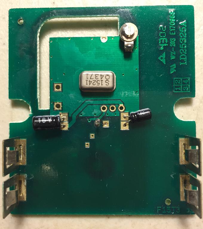
Back view of the board. You can see the coil antenna as the top right curved trace.
Referring
to the back of the board, it is easy to see that the large trace on the
bottom of the image and the square at the top is the ground reference
plane. The processor is clearly encapsulated in the black
blob,
and the RF oscillator/transmitter is at the top. This latter
module is
controlled probably by the crystal in the can on the front of the
board. One can also see an antenna on the board traces at the
top-right coupled to by a variable capacitor. It appears (since there
is a crystal) that the capacitor adjust the antenna tuning for maximum
output (and should not affect the frequency). The actual
temperature sensor appears to be a small part in the front middle of
the board that sits in a hole in the front of the small transmitter box.
There are fortunately only two traces that cross into the square ground plane at the top, and one of which is power, the other is easily determined to be serial output. These signals are easily accessed by the three adjacent round holes in the middle of the board. These are power (left on back), ground, and serial output (right on back).
Putting the signal on the serial output line on the scope shows that the following data protocol (at room temperature).
- There are three groups of data transmissions. Each last about 85-87 msec with a 24 msec pause between them.
- Zooming into each group, it is clear that all the 'low' periods are the same duration, and there are two 'high' durations. This is similar to the Sony SIRCS protocol, and so we can characterize a '1' bit is a long high and a low, while the '0' bit is a short high and a low.
- The timing of the '1' is 1.36 msec high, and 920 usec low. The '0' is 560 usec high and 920 usec low. For 50% duty cycle data, the average bit time is 1.9 msec, so there are about 46 bits per group.
- When
the board is initially powered up, the chip transmits a packet every
six seconds. After about four minutes, the output rate drops
to
about one per minute.