| Home | Job | Pinball | Photo Album | Automotive | Press/Awards | Contact |


During a visit to the 2006 Virginia Pinball Tournament, we got a chance to play the Medieval Madness (MM) machine. The kids and I enjoyed playing this machine, and found that the hype around it is well founded. This machine is well-known as the most collectable and enjoyable machine of all, and consistently ranks first in polls. I purchased mine from Randy Paris and it was in the unshopped condition. This is the way I prefer to buy pins as I enjoy the process of completely tearing down the machine to clean and refurbish all the parts.
This machine's playfield features a catapult that fires the pinball, trolls that pop up from the playfield, and an exploding castle with a drawbridge and iron drop-gate.
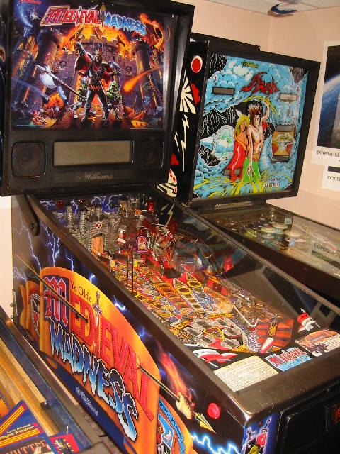
View of the side of the
cabinet.
Note the roasted marshmallow on the spear.

Lower playfield.
Lower playfield.
The renovation process
All the plastics were replaced with a New Old Stock (NOS) set from Marcos Specialties. I also bought various parts such as target switches, the steel castle gate, and dragon wings. Extensive use of laser printed graphics were used to make overlays and decals such as for the castle drawbridge, troll flaps and other locations. The plastic ramps were stripped, cleaned and then flame polished. The metal ramps responded well to a rubbing of 'Brasso' (unlike the IJ ramps, which did not), and came out bright and shiny.

Top right corner of playfield at the start of the renovation process. This machine has seen a lot of wear.
The top right area after the renovation. Everything was removed, cleaned, and repaired/restored as needed.
The playfield was touched up and overlays were printed to repair the surface.
View from the left before renovation. Note the dirty ball guides and ramps. Also the wear around
the castle doors.

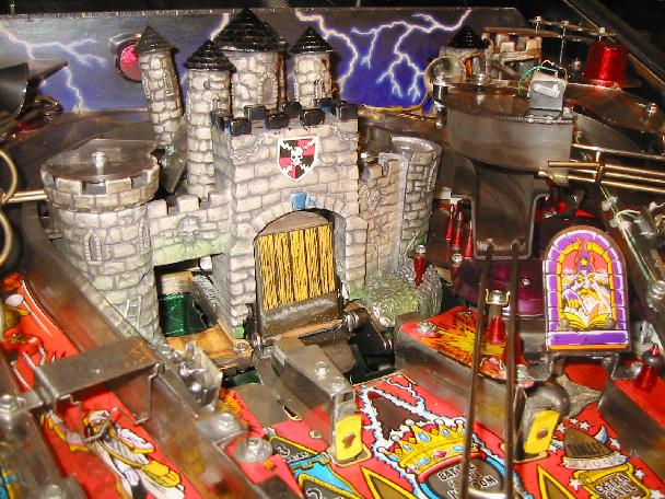
Same view after cleaning and repairing (before ramps have been put back). The castle has been clearcoated and looks like new.
All metal ball guides have been polished and regrained. Overlays were added to cover the spots of worn playfield.
Protectors were added for the high wear spots around the castle.

Same shot with all hardware installed including ramps and NOS plastic pieces. Note my experimentation with covers for the ramp
switches using wood decals. I thought their exposed appearance detracted from the playfields aesthetics.
Repair Tips, Mods and Rework Notes
Repairing the castle
walls
The edge of the castle gate was broken on the left hand side, so I decided to purchase a new one. However, when it arrived, I saw how little was broken, and decided to repair the existing one. Using fiberglass tape and epoxy, I rebuilt the left entrance. I also touched up the footers of all the towers and clearcoated the entire castle with non-yellowing polyurethane. This is the method first developed on the Space Shuttle ramps.

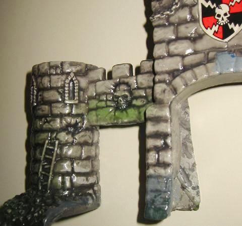
Repaired castle gate entrance. For a photo of this installed into the machine, see below.
overlay. It is then covered with mylar afterwards.
I started by shooting a photo of the area with a ruler in the field of view. A resolution of about 300 dpi is a good target to achieve. I then edited the image to add the missing parts back in with PhotoShop. The image was then printed onto both photo paper and vinyl media from mediastreet.com. The former product is 6.8 mils thick, while the latter is 6.5 mils (normal office paper is 4 mils). I found that the former worked better in terms of the image quality in the solid areas. Whenever the vinyl was stretched, the colors would crack, so I used photo paper. I then glued the paper down with dry glue from a glue stick (prevents wrinkling of the paper), and covered the area with mylar. I later found that it is best to seal the step between the paper and playfield with a bead of clear polyurethane. If this is not done, the thick mylar will not adhere right at the edge of the step.
This entire process is easily reversed or removed with freeze spray and alcohol, so I can elect to touch up and clearcoat later if desired.
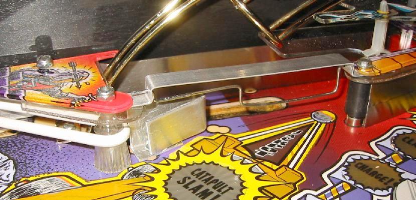
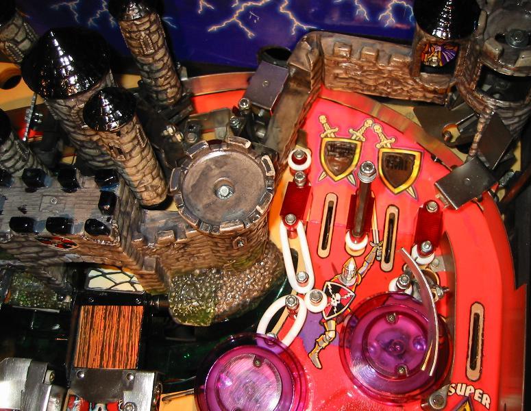
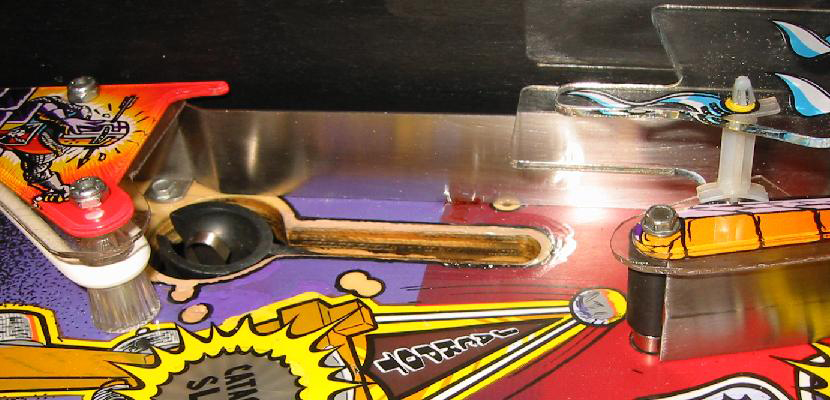
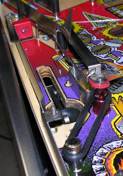
The finished catapult area with the ball guide and ball gate that I made myself. Note that I chose to put the ball gate UNDER
the playfield plastics so that it would not obscure them.
I was trying to figure out how to get 300 dpi images of the head and tail of the spear for the cabinet overlays.
I debated e-mailing other owners and looked at all kinds of websites for a decent image. I also contemplated
drawing the artwork from scratch.
Then I realized that the side-art is the same on both sides! To get the artwork of the left front, I just
needed to photograph the right back, and vice versa. I just filled in the missing parts with Photoshop.

Middle of the playfield before renovation. There was damage on the upper castle,
Magic Shield and the Scroll.
The lower playfield after installation of the overlays from Classic Arcades.

Closeup of the overlays. They are spot on. Even with the naked eye, it is difficult to see the dividing line between overlay
and original playfield. I chose to not replace the insert artwork on the lower right castle.
Links/Bookmarks
Project Log
The edge of the castle gate was broken on the left hand side, so I decided to purchase a new one. However, when it arrived, I saw how little was broken, and decided to repair the existing one. Using fiberglass tape and epoxy, I rebuilt the left entrance. I also touched up the footers of all the towers and clearcoated the entire castle with non-yellowing polyurethane. This is the method first developed on the Space Shuttle ramps.
Repaired castle gate entrance. For a photo of this installed into the machine, see below.
Printing overlays
Some areas of the playfield were worn, and I decided to print my own overlays to touch them up.

Photos of the exit of the moat upkicker on the left of the
playfield. Before and after adding theSome areas of the playfield were worn, and I decided to print my own overlays to touch them up.
overlay. It is then covered with mylar afterwards.
I started by shooting a photo of the area with a ruler in the field of view. A resolution of about 300 dpi is a good target to achieve. I then edited the image to add the missing parts back in with PhotoShop. The image was then printed onto both photo paper and vinyl media from mediastreet.com. The former product is 6.8 mils thick, while the latter is 6.5 mils (normal office paper is 4 mils). I found that the former worked better in terms of the image quality in the solid areas. Whenever the vinyl was stretched, the colors would crack, so I used photo paper. I then glued the paper down with dry glue from a glue stick (prevents wrinkling of the paper), and covered the area with mylar. I later found that it is best to seal the step between the paper and playfield with a bead of clear polyurethane. If this is not done, the thick mylar will not adhere right at the edge of the step.
This entire process is easily reversed or removed with freeze spray and alcohol, so I can elect to touch up and clearcoat later if desired.
The door on the left of
the main
castle gate opens to allow the ball to 'crash through' the
wall.
The base of this door is just the wood of playfield itself.
This
had a great deal of wear on it, so I decided to make a protector for
the base and the pocket behind it.

Closeup of the protectors for the door on the left of the gate. Here is the before picture.
One additional note is that the decal for wood of the castle drawbridge
was
printed using a scan from ballsofsteel.net. This was printed
onto
vinyl with a color laser and then laminated with clear mylar.
The end result looks very close to the fragment that was on the bridge
when I bought
the machine. The metal parts of the drawbridge were spray
painted
with black
gloss enamel.
Merlin Hole Protector
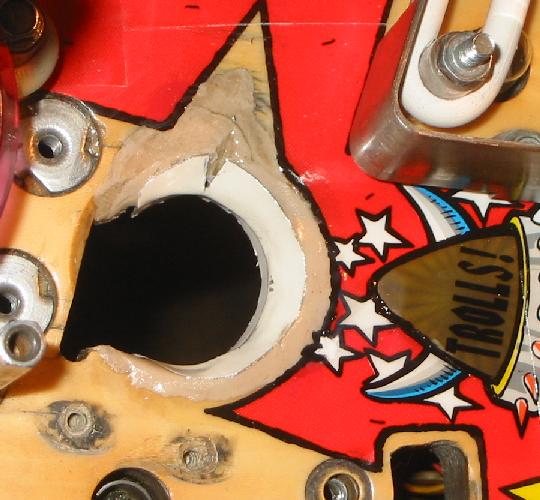
As with many MM's the Merlin Hole on my machine was worn. In the initial renovation, I restored the hole with epoxy wood putty and touched up the paint (similar to how Dave did his). It turned out very nice, but after a few months of play, the wood putty cracked and broke away. Clearly, I needed a protector for the wood of the playfield. These are available as a set (see links below), but I decided to build my own.

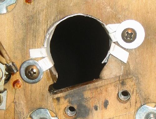
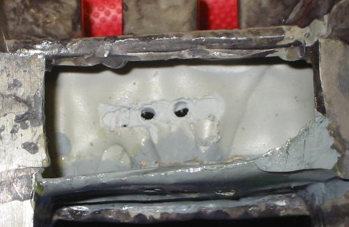
Appearance of the Merlin Hole before the protector was installed. Note the remaining wood putty
restoration on the top left corner of the hole. The right side of the hole is showing
wear and the missing wood putty.
The biggest challenge in making this protector was the flared round shape at the surface of the playfield. Unlike the previous protector that I made, this one needed to curve in two directions. I considered several methods of making this flare, including hammering the metal on a form, but after some roaming around the house and brainstorming, I found a solution that worked for me. The hole in the playfield is 1 1/4" in diameter (ball is 1 1/16"). I hit on the idea of using an empty 35mm film container and a hose clamp as the form for bending the flare in a sheet of aluminum.

The aluminum sheet is pre-bent in a cylinder, and then wrapped onto
an empty 35 mm film can tube. Then the edge is gradually flared out with a pair of pliers
padded with a paper towel (to prevent scratching the surface).
I made sure 3/8" of the aluminum sheet was above the edge of the film container, and proceeded to gently bend the exposed lip into a flare. Make small bends all the way around, and make repeated passes to gradually bend the top open into a flared funnel. After two tries, this produced a very nice shape that fit very well in the playfield. I then snipped tabs in the opposite end, and bent it in a fan to form a lip to fasten to the under side of the playfield.

The almost finished protector. After this photo was shot, and fit checked in
the playfield, the unused tabs were cut off. Note the notch cut in the flare
to match the funnel tip in the Merlin Hole.
The resulting flared cylinder was very pleasing to the eye and fit very nicely in the playfield. I then used wood putty to snugly fit the protector onto the playfield. The result is that the space between the wood and the protector was completely filled. This allows the shock of the ball to be transferred to a large surface area, and should be very durable. I was able to make the top rim of the flare flush with the top face of the playfield, and filled in the missing wood with the wood putty. After a few minutes of set time, the wood putty was just the right consistency to allow forming and sculpting with my finger tips to make a level transition from the lip of the protector to the surface of the playfield. No sanding was needed, so I did not have to risk scratching the playfield surface.
The protector assembled into the bottom of the playfield.
After the epoxy wood putty had cured, I touched up the area with acrylics using a sewing needle as the paint brush. I was a bit out of practice, but I did not do too badly. The red was "Crafter's Edition Real Red #72007", an excellent match. The white was Titanium White.
Installed protector lined with the wood putty and touched up with acrylics.
After touchup, the area was brushed with clearcoat and then mylared.
Note the excellent match on the red color. It is undetectable.
Before reinstalling the Merlin Hole upkicker solenoid, I attached a
trim piece of adhesive rubber onto the scoop of the Merlin Hole (no
photo). This was very effective in cushioning the pinball as
it
comes into the Merlin Hole. A few test rolls of the ball into
the
Merlin Hole showed that the whole assembly worked flawlessly.
Balls did not bounce out of the hole, and the rubber strip and snug
protector freezes the ball as soon as it hits the scoop.
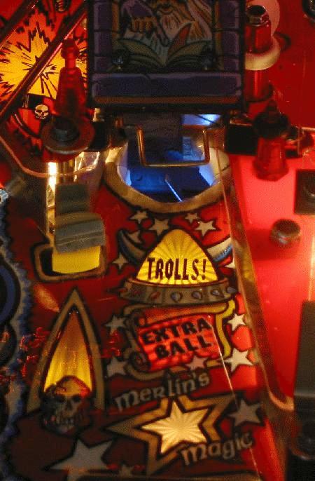
Photo of the final assembly. Note an experiment shown here with a white LED
lighting up the Merlin Hole. Not as impressive as on my IJ, so I will
be experimenting with color and angle.
Protector for plastics
Using some Lexan, I made protectors for plastics that are in the line of fire. This includes all the plastics at the front of the castle. In the picture below, the bottom plastic had a previous protector that was broken by ball hits. I made the second revision more beefier. Were it not for the protector, the valuable plastic would no doubt have been broken. See them installed in the picture above (Merlin Hole protector completed). The Lexan was cut with tin snips, and then filed smooth to finish the edge.

The edges of these plastics are protected from ball hits.
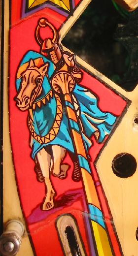
Touching up the
dragon and
trolls
The dragon on the right of the playfield is a large part of the decorative package. I decided to touch it up to let it stand out. This was done by first wiping down the dirt and dust with an alcohol dampened paper towel and then repainting the white accents and then brushing clear polyurethane over the whole body. Although I do not have any 'before' pictures, the results are a great improvement.
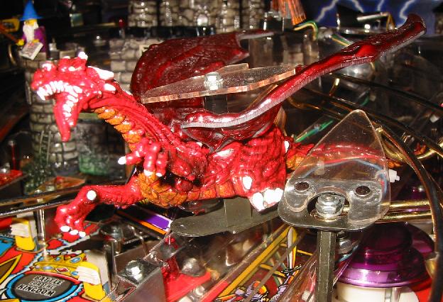
Each tooth and claw was individually painted.
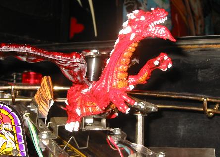
The orange on the dragon's throat was also touched up.
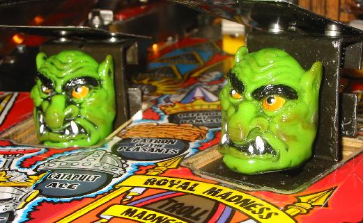
In addition to the dragon, I also touched up and clearcoated the trolls as they get a lot of ball hits.
The teeth and nose received the bulk of the detailing treatment.
Since the original color is impervious to alcohol, but the touchups and clear disolve in it, I can remove this mod in the future.
However, I think it looks quite good.
Others have added lights to their dragon eyes by drilling holes through it, and inserting LEDs.
The catapult
pocket
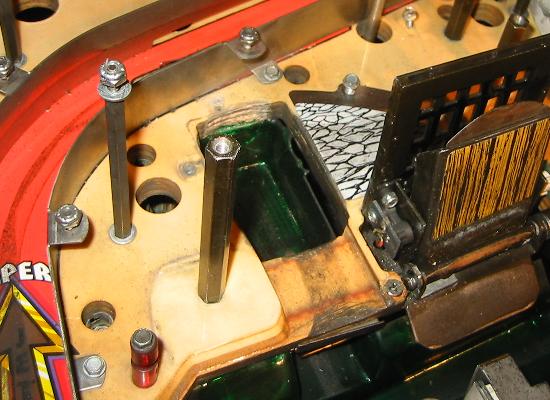
One area that needed a lot of work was the pocket for the catapult on the left hand side. There is supposed to be a ball guide and ball gate at the entrance, but it must have come loose and some operator used some wood screws (gasp!) to replace this hardware. As reference, this is how the prototype game looks (the two wire guides match the layout of the playfield), while this is a picture of the guide on the production machine. Also, another image courtesy of M. Reynolds.

Picture of the catapult pocket before restoration. Note the dirty opening for the catapult in the playfield and the wood
screws used to replace the ball guide.
The catapult area after repair. Note the clear protectors that I made for the NOS plastics and the repaired playfield.
Closeup of the protectors for the door on the left of the gate. Here is the before picture.
I made the protectors
out of aluminum
sheets. The one for the base of the door was then covered
with a
decal that I made by shooting a photo of the castle foundation and
cloning it into a pattern. This protector is held in place by
the
metal plate under the playfield. Then the pocket behind the
door
was lined with aluminum that was painted dark green to match the moat
color.
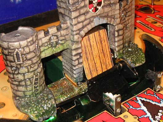
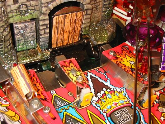
Protector with the castle wall in place.
Protector with the castle wall in place.
Merlin Hole Protector
As with many MM's the Merlin Hole on my machine was worn. In the initial renovation, I restored the hole with epoxy wood putty and touched up the paint (similar to how Dave did his). It turned out very nice, but after a few months of play, the wood putty cracked and broke away. Clearly, I needed a protector for the wood of the playfield. These are available as a set (see links below), but I decided to build my own.
Appearance of the Merlin Hole before the protector was installed. Note the remaining wood putty
restoration on the top left corner of the hole. The right side of the hole is showing
wear and the missing wood putty.
The biggest challenge in making this protector was the flared round shape at the surface of the playfield. Unlike the previous protector that I made, this one needed to curve in two directions. I considered several methods of making this flare, including hammering the metal on a form, but after some roaming around the house and brainstorming, I found a solution that worked for me. The hole in the playfield is 1 1/4" in diameter (ball is 1 1/16"). I hit on the idea of using an empty 35mm film container and a hose clamp as the form for bending the flare in a sheet of aluminum.
The aluminum sheet is pre-bent in a cylinder, and then wrapped onto
an empty 35 mm film can tube. Then the edge is gradually flared out with a pair of pliers
padded with a paper towel (to prevent scratching the surface).
I made sure 3/8" of the aluminum sheet was above the edge of the film container, and proceeded to gently bend the exposed lip into a flare. Make small bends all the way around, and make repeated passes to gradually bend the top open into a flared funnel. After two tries, this produced a very nice shape that fit very well in the playfield. I then snipped tabs in the opposite end, and bent it in a fan to form a lip to fasten to the under side of the playfield.
The almost finished protector. After this photo was shot, and fit checked in
the playfield, the unused tabs were cut off. Note the notch cut in the flare
to match the funnel tip in the Merlin Hole.
The resulting flared cylinder was very pleasing to the eye and fit very nicely in the playfield. I then used wood putty to snugly fit the protector onto the playfield. The result is that the space between the wood and the protector was completely filled. This allows the shock of the ball to be transferred to a large surface area, and should be very durable. I was able to make the top rim of the flare flush with the top face of the playfield, and filled in the missing wood with the wood putty. After a few minutes of set time, the wood putty was just the right consistency to allow forming and sculpting with my finger tips to make a level transition from the lip of the protector to the surface of the playfield. No sanding was needed, so I did not have to risk scratching the playfield surface.
The protector assembled into the bottom of the playfield.
After the epoxy wood putty had cured, I touched up the area with acrylics using a sewing needle as the paint brush. I was a bit out of practice, but I did not do too badly. The red was "Crafter's Edition Real Red #72007", an excellent match. The white was Titanium White.
Installed protector lined with the wood putty and touched up with acrylics.
After touchup, the area was brushed with clearcoat and then mylared.
Note the excellent match on the red color. It is undetectable.
Photo of the final assembly. Note an experiment shown here with a white LED
lighting up the Merlin Hole. Not as impressive as on my IJ, so I will
be experimenting with color and angle.
A dozen test games
showed that the
whole assembly worked without problems. One noticeable thing
is
that the ball no longer makes a sound when it hits the hole and shows
it is being cushioned and just goes 'dead' as soon as it its the
scoop. This matches my experience at Martin R's place
when he gave me the
sheet of rubber material. The part of this project that was
most
satisfying is
finding ways to bend the the metal into new shapes. This
could be
useful in the future when making other protectors.
Protector for plastics
Using some Lexan, I made protectors for plastics that are in the line of fire. This includes all the plastics at the front of the castle. In the picture below, the bottom plastic had a previous protector that was broken by ball hits. I made the second revision more beefier. Were it not for the protector, the valuable plastic would no doubt have been broken. See them installed in the picture above (Merlin Hole protector completed). The Lexan was cut with tin snips, and then filed smooth to finish the edge.
The edges of these plastics are protected from ball hits.
The dragon on the right of the playfield is a large part of the decorative package. I decided to touch it up to let it stand out. This was done by first wiping down the dirt and dust with an alcohol dampened paper towel and then repainting the white accents and then brushing clear polyurethane over the whole body. Although I do not have any 'before' pictures, the results are a great improvement.
Each tooth and claw was individually painted.
The orange on the dragon's throat was also touched up.
In addition to the dragon, I also touched up and clearcoated the trolls as they get a lot of ball hits.
The teeth and nose received the bulk of the detailing treatment.
Since the original color is impervious to alcohol, but the touchups and clear disolve in it, I can remove this mod in the future.
However, I think it looks quite good.
Others have added lights to their dragon eyes by drilling holes through it, and inserting LEDs.
One area that needed a lot of work was the pocket for the catapult on the left hand side. There is supposed to be a ball guide and ball gate at the entrance, but it must have come loose and some operator used some wood screws (gasp!) to replace this hardware. As reference, this is how the prototype game looks (the two wire guides match the layout of the playfield), while this is a picture of the guide on the production machine. Also, another image courtesy of M. Reynolds.
Picture of the catapult pocket before restoration. Note the dirty opening for the catapult in the playfield and the wood
screws used to replace the ball guide.
I repaired the area by
removing the
wood screws and then sealing/glueing the open wood with epoxy clamped
down hard by a C-clamp and a teflon block. This produced a
flat
area that I could paint with acrylics. The opening of the
catapult was then sanded to reveal the wood, and then touched up with
acrylics. The touchups were then brushed with Olympic
water-based
polyurethane. It turned out better than I expected.
Whereas
before the restoration, the catapult opening in the playfield felt
dirty and rough, it felt like I was touching fine furniture cabinetry
after the rework.
For the purple, I mixed titanium white and "DecoArt's Dioxazine Purple". For the yellow, I used "Crafter's Edition Bright Yellow #72010". For the red, I mixed black with "Crafter's Edition Real Red #72007".
For the purple, I mixed titanium white and "DecoArt's Dioxazine Purple". For the yellow, I used "Crafter's Edition Bright Yellow #72010". For the red, I mixed black with "Crafter's Edition Real Red #72007".
The catapult area after repair. Note the clear protectors that I made for the NOS plastics and the repaired playfield.
Since the ball guide and
ball gate
were missing, I had to rebuild those. I had
attempted to find them at the 2006 Allentown Pinball Show, but to no
avail. Also, places like Marcos did not stock a ball gate of
this
size and configuration (5 1/8" from hole-hole with half-width
opening). I made mine from aluminum cut with an
industrial shear, and the stainless wire was obtained at no charge from
a welding supply shop.
The finished catapult area with the ball guide and ball gate that I made myself. Note that I chose to put the ball gate UNDER
the playfield plastics so that it would not obscure them.
Making Plastics
Something noticed by other collectors is that there is seemingly a missing plastic on the barrier behind the left yellow target switch. I decided to use this as an opportunity to experiment with making playfield plastics.
The plastic installed. It is the one behind the yellow target. Without the plastic.
One funny note about this part of the project. Something noticed by other collectors is that there is seemingly a missing plastic on the barrier behind the left yellow target switch. I decided to use this as an opportunity to experiment with making playfield plastics.
The plastic installed. It is the one behind the yellow target. Without the plastic.
Prior to installing the
NOS plastics
set, I scanned them all at 300 dpi. Using one of these files,
I
created the artwork for the new plastic, and printed this on glossy
photo paper with a laser printer. I then cut out a bullet
shaped
piece of Lexan (the same stuff I use to make protectors), and used
plastic glue (Duco Cement) to glue the paper on. This was the
trickiest part. It is important to put enough glue on to full
wet
the interface between the surfaces so that there are no air
bubbles. This may cause some to squeeze out the
sides. Dry
this layup overnight with pressure from some heavy objects.
If
the layer of glue is too thick, it may darken or cloud the image, so
the right amount is important.
Cabinet Decals
The cabinet had some damage of the artwork along the front near the flipper buttons. I decided not to replace the entire cabinet decal set due to cost and lack of experience with cabinet decals. Seeing the good results obtained with the playfield, I decided to print overlays for the cabinet.
Perhaps due to luck, or experience gained from the playfield work, I was able to match the colors and darkness on the first proof print. I then printed the artwork in sections on glossy photo paper with a Laser printer.
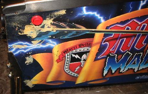

State of the front of the cabinet before the restoration.


Cab after application of printed overlays.
After installation of the overlays, I added protectors for the flipper buttons and felt pads for the legs.
You may be able to see a slight ghost near the flipper buttons due to the former.
Cabinet Decals
The cabinet had some damage of the artwork along the front near the flipper buttons. I decided not to replace the entire cabinet decal set due to cost and lack of experience with cabinet decals. Seeing the good results obtained with the playfield, I decided to print overlays for the cabinet.
Perhaps due to luck, or experience gained from the playfield work, I was able to match the colors and darkness on the first proof print. I then printed the artwork in sections on glossy photo paper with a Laser printer.
State of the front of the cabinet before the restoration.
Cab after application of printed overlays.
After installation of the overlays, I added protectors for the flipper buttons and felt pads for the legs.
You may be able to see a slight ghost near the flipper buttons due to the former.
Notes on making overlays:
- Use a diffuse light source such as a large compact
fluorescent
lamp. This is because you will be shooting normal to the
surface,
and the reflection of the flash will be a hindrance. CF lamps
have good color spectrum.
- Use a tripod for the camera, and hold the lamp such that
no
reflection
can be seen in the image. For a very stable shutter release,
use
the timer function on the camera.
- Shoot a low distortion base image of the damaged
area.
Use
an inch ruler in the field of view. It is important to have
the
camera positioned over the center of the area of interest for the
lowest distortion, and shoot from a distance and zoom in.
- For the new artwork, shoot close-ups of the various areas of interest. Ideally, 300 dpi is optimal. Thus a 5 MegaPixel camera (2500 pixel width), should cover an area no larger than 8" across. Also, it is better to keep your distance and zoom into the area for less distortion. Don't forget to use a macro lens if you are very close.
- Using a program like Photoshop, import the base image first. Increase the canvas size to about 300 dpi. In other words, increase the size of the image (in pixels) depending on the size of the final printed artwork.
- Import each of the close-ups on separate
layers. One at a
time, set their transparency to 50%. Use the "distort"
function
to
drag the corners so that the close-up lines up with the base
image. This undoes the distortion of the close-up images, and
is
a means to stitch the close-ups together. Be warned that the
Photoshop file, with all the layers, may get very large (100MByte in
cases).
- Use the "eraser" in diffuse setting to blend one layer with another. Also, the contrast and brightness of each layer should be adjusted to match. It helps to make the transition at natural lines in the image. The eye dropper tool is useful to add areas of a specific color, and cloning is very useful for textures.
- When printing, include a copy of the inch ruler in all the images. This will allow you to scale it approximately right. Use a proof that is marked up with features to get the final size correct. I have found glossy photo paper printed with a color laser to produce the best results.
- Seal the printed sheets with a clear poly such as "Triple
Thick". This will provide a measure of moisture and abrasion
resistance.
- For the glue, use glue from a glue stick. This dry form of glue will not cause the paper to ripple, and will give you a chance to reposition. When repositioning, be careful not to stretch the paper as the laser print may crack (more of a problem with vinyl).
- Apply the bottom-most overlays first, and allow the upper
ones
to overlap them. This will hide the seams better.
- Cut the paper with a very sharp pair of scissors. In some cases, you will see the edge of the paper showing once it has been glued. Use acrylic paint of the appropriate color to touch this edge up. Before the paint dries, wipe with a paper towel to remove the paint from the face of the overlay and the cab. Paint should only be left on the very edge of the paper causing it to essentially disappear.
- If you apply mylar over a transition between original surface and overlay, put a few beads of clearcoat down at the edge so that it forms a 'ramp' in the transition zone. This is because the mylar is usually very stiff, and will not adhere right at the transition, leaving a hazy edge. The clearcoat ramp will prevent this.
- Just like my playfield overlays, the materials were
chosen so
that they be readily removed later in case I decide to redo the overlay
or strip the side-art completely.
I was trying to figure out how to get 300 dpi images of the head and tail of the spear for the cabinet overlays.
I debated e-mailing other owners and looked at all kinds of websites for a decent image. I also contemplated
drawing the artwork from scratch.
Then I realized that the side-art is the same on both sides! To get the artwork of the left front, I just
needed to photograph the right back, and vice versa. I just filled in the missing parts with Photoshop.
Middle of the playfield before renovation. There was damage on the upper castle,
Magic Shield and the Scroll.
The lower playfield after installation of the overlays from Classic Arcades.
Closeup of the overlays. They are spot on. Even with the naked eye, it is difficult to see the dividing line between overlay
and original playfield. I chose to not replace the insert artwork on the lower right castle.
The overlays from
Classic Arcade are
printed on a very high quality material. During the
installation,
I had to reposition the Magic Shield overlay, and despite the pulling
did not stretch or crack the ink on it. It laid back down
just
like I had applied it the first time. This kind of treatment
would not have been possible with the vinyl or paper overlays that I
printed myself.
My notes:
My total cost in overlays was about $140. This includes $70 for the complete set of all inserts (which I ended up not using). The remainder was for 6 other overlays, including the Scroll, the Magic Shield, a overlay to cover the top and right two castles around the Magic Shield, the "Dragon Snack", the "Clash" insert, and one star shaped insert. Considering that all but one of these was custom made for me, I think the price is very reasonable. I was also sent two "scrap" overlays to experiment with my waxing, cleaning and clearcoating methods. As far as I could tell, the overlays are impervious to the clear coat, IPA alcohol and the Carnauba wax that I use (Turtle Wax).

Photos of some of the overlays that I received. Marcos sells an overlay of the scroll
(without the custom stone work) for $12. The Magic Shield is also available.
To contact Jeff at Classic
Arcades, use the e-mail:
mcafee@adelphia.net, or his phone at (570)-819-1570. At the
time
of my ordering, he was very busy, and e-mail response was
slow.
The best way to reach him was by phone.
My notes:
- Cut away any excess backing material so that you can
preposition
the overlay in the intended area. Make sure you like the way
it
lines up. You may also want to trim the overlay to have the
division lines fall along features in the artwork. An example
of
this is the stone work next to the Scroll in the image above.
- Clean the area well with alcohol to remove finger grease and playfield wax. Make sure there is no loose material or flaking paint as it will show under the overlay.
- Peal one corner of the overlay backing and fold flat to expose the adhesive.
- Position the overlay without sticking the pealed back area, lining up all the features you used before, then stick the pealed-back portion.
- Gradually peal the backing away, lining up the features as you go. Make sure no bubbles get trapped.
- If you do trap bubbles, make a small puncture with a needle. Do this in a light area as this is less obtrusive in case you cut some ink away.
- (Optional) Seal the edge of the overlay with some clearcoat such as Olympic water-based polyurethane. I had used this previously to clearcoat the Flash with good results. This sealant is meant to keep out playfield wax, and to provide a "ramp" for the ball to transition from the playfield to the overlay.
- If you do not seal with clear, I would recommend you apply
mylar
over the area.
- In the areas where the overlay is clear, I removed the old clear part with a sharp Exacto knife. This is to prevent a double image in the clear area. I do not know if this is strictly necessary.
My total cost in overlays was about $140. This includes $70 for the complete set of all inserts (which I ended up not using). The remainder was for 6 other overlays, including the Scroll, the Magic Shield, a overlay to cover the top and right two castles around the Magic Shield, the "Dragon Snack", the "Clash" insert, and one star shaped insert. Considering that all but one of these was custom made for me, I think the price is very reasonable. I was also sent two "scrap" overlays to experiment with my waxing, cleaning and clearcoating methods. As far as I could tell, the overlays are impervious to the clear coat, IPA alcohol and the Carnauba wax that I use (Turtle Wax).
Photos of some of the overlays that I received. Marcos sells an overlay of the scroll
(without the custom stone work) for $12. The Magic Shield is also available.
The idea for this mod
came from Doug
Grant, an RGP member. He drilled out the windows of
the left
tower and skull of the castle to insert lights into them.
Since I
had a spare castle front, I decided to try this mod also.

The LEDs used for the skull eyes are 2 mm in size.
The drilled out eye holes of the skull.
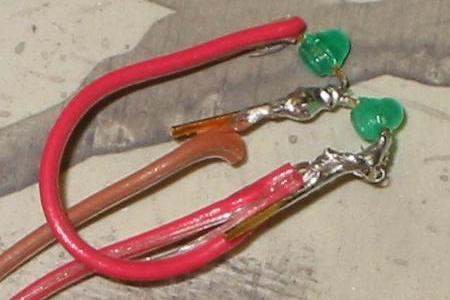
The LED cluster assembly for the skull eyes.
The skull eye assembly glued into place, and the tower LED (yellow) ready to install.
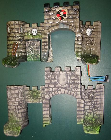
The castle front was further touchup painted, and this is the comparison with
an NOS unit.

The finished product. All LEDs were wired into the GI circuit so they come on and off with game play.
Note the Lego Merlin (actually Dumbledore from Harry Potter) on the left tower.
Page 2 of MM mods and tech tips
The LEDs used for the skull eyes are 2 mm in size.
The LEDs for the skull
eyes are T-3/4
units that are about 2mm in size. I do not think T-1's (3mm)
or
larger would look good. I only had green color ones, and they
were embedded in a plastic holder. After removal, they look
like
the right hand of the picture above.
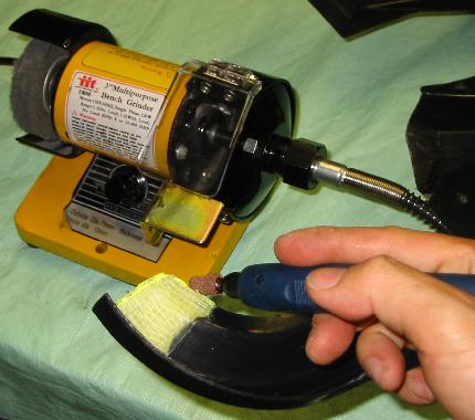
The drilled out eye holes of the skull.
After drilling out the
eye holes, I
milled a channel for the leads of
the LED with my handheld Dremel
attachment. This tool allows fine control, and with
an
end-mill can carve out material in a controlled fashion. The
channel allows them to be positioned as close to the front face as
possible. Be
sure to angle the LED upwards towards the player's eyes.
The LED cluster assembly for the skull eyes.
An initial test showed
that the
forward voltage drop of the green LEDs was too large to allow them to
be used on the lamp marix. So my initial plan of having the
eyes
light up as the game is played would not work. I decided to
then
put the LEDs on the GI circuit. Since this is AC on the MM, I
put
the two LEDs in parallel, but back-to-back (anode to
cathode).
This will cause one LED to light per half cycle. A
current-limiting resistor of 51 Ohms was used in series with the GI
circuit. The resulting AC current is about 48mArms, or about
24
mArms per LED.
The skull eye assembly glued into place, and the tower LED (yellow) ready to install.
The LEDs are glued into
the castle
with hot glue. Make sure to angle the LEDs upwards towards
the
players eyes. This will make the whole assembly the most
efficient. For the right most skull, this will involve
angling
the LED the most. This is because that skull looks downward
slighly. Be sure to only drill a small hole through the eye
sockets, and then make a larger angled hole in the back. This
prevents removing excess material from the skull front.
I then added paint touchups to the castle front in the following areas:
I then added paint touchups to the castle front in the following areas:
- Ladder on left. Painted the wood brown.
- Chains on castle top. Painted them metallic black.
- Skulls. Painted them Wicker White.
- Grapple hook and rope. Metallic black and white.
The castle front was further touchup painted, and this is the comparison with
an NOS unit.
To allow easy removal of
the castle,
I included in inline connector consisting of a row of DIP
sockets. This row plugs into a similar unit, and allows me to
separate the ribbon cable that powers the LEDs.
For the tower, I used my end mill again to mill out the window openings. There is a metal rod that passes through the tower that presented a special challenge. After some experimentation, I found that I could use a single high-intensity yellow LED (courtesy of Martin Reynolds) to light up the windows. First, I applied clear tape on the inside of the windows so they would diffuse light. As shown in the figure below, the beam of the LED is directed at the left window, and causes it to light up brightly. At the same time, the LED is positioned directly behind the right window so that the player has a direct line of sight to it (through the clear tape). This allows both windows to be brightly lit with the minimum of power. Finally, the whole ensemble is fastened by hot glueing the wire bundle into the castle wall above the left skull. Once glued in place, the wires can be slightly bent to tweak the alignment of the beam onto the left window.

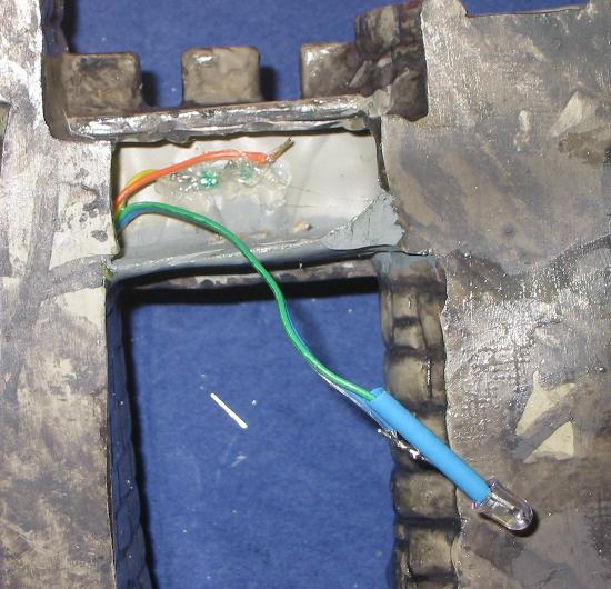
Top view of castle tower shows the placement of the yellow LED
For the tower, I used my end mill again to mill out the window openings. There is a metal rod that passes through the tower that presented a special challenge. After some experimentation, I found that I could use a single high-intensity yellow LED (courtesy of Martin Reynolds) to light up the windows. First, I applied clear tape on the inside of the windows so they would diffuse light. As shown in the figure below, the beam of the LED is directed at the left window, and causes it to light up brightly. At the same time, the LED is positioned directly behind the right window so that the player has a direct line of sight to it (through the clear tape). This allows both windows to be brightly lit with the minimum of power. Finally, the whole ensemble is fastened by hot glueing the wire bundle into the castle wall above the left skull. Once glued in place, the wires can be slightly bent to tweak the alignment of the beam onto the left window.
Top view of castle tower shows the placement of the yellow LED
The yellow LED also uses
a 51 Ohm
series resistor. The resulting
DC current reading is about 34mA. Compare that to a current
of
150mA of a #47 bulb, and you can see that the LEDs represent a small
load to the GI circuit.

Schematic of the lighting circuit.
Schematic of the lighting circuit.
The finished product. All LEDs were wired into the GI circuit so they come on and off with game play.
Note the Lego Merlin (actually Dumbledore from Harry Potter) on the left tower.
Page 2 of MM mods and tech tips
- Other owners
- Dave Schulpius
- Ceegary
- Internet Pinball Database
- Kansas Pinball (repainting castle)
- Link to scans
of NOS
MM plastics at 300 dpi.
- Casting
one's own castle
- Another pinball poll
- Rule Sheets/How to play
- Detailed playfield pictures
- Creating your own decals.
Project Log
- April 22 2006 - Purchased machine from Randy Paris.
- April 30 2006 - Top of playfield stripped. Ordered $400 of parts from Marcos and overlays from Classic Arcades. New: plastics set, balls, dragon wings, steel castle gate, castle front, targets switches, overlays, etc.
- April 31 2006 - All mylar removed and playfield washed with alcohol and Magic Eraser.
- May 2 2006 - Repaired castle entrance.
- May 8 2006 - Experimented with printing overlays.
- May 12 2006 - Upper part of playfield done.
- May 15 2006 - Playfield is finally reassembled. We play our first few games! Last thing to do is to put in overlays from Classic Arcades.
- May 17 2006 - Finished catapult gate.
- May 22 2006 - Cabinet overlays.
- May 26 2006 - Playfield overlays.
- July 8, 2006 - Added remote battery mod to the MM.
- July 16, 2006 - Solved intermittent ball launch problem. See here.
- July 22, 2006 - Lit castle mod installed.
- August 5, 2006 - Protectors for Merlin Hole and plastics installed.
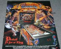
- August 11, 2006 - Bought the large (34"x24") poster for this machine for $20+$10. Before that, I purchased the flyer for it also ($5+$5). Both look nice in my pin room.
- October 2, 2006 - Added bass boost.
- November 24, 2006 - Installed modified (electronic) backboard.
(c) 2006 Edward Cheung, all rights reserved.