| Home | Job | Pinball | Photo Album | Automotive | Press/Awards | Contact |

Williams
Pinball CPU/Computer Board Repair - Page 2
Note: I have several repaired
System 9 and 11 boards for sale, and I also repair these boards. Please contact me for
details.
6802/6808 Adapter for HP Logic Analyzers
In August 2009, I made an adapter to easily connect my logic analyzer to the address, data, and control lines of the CPU chip. It allows complete access to the operation of the CPU board core. This board is a modification of the 68B09 adapter from the WPC project.
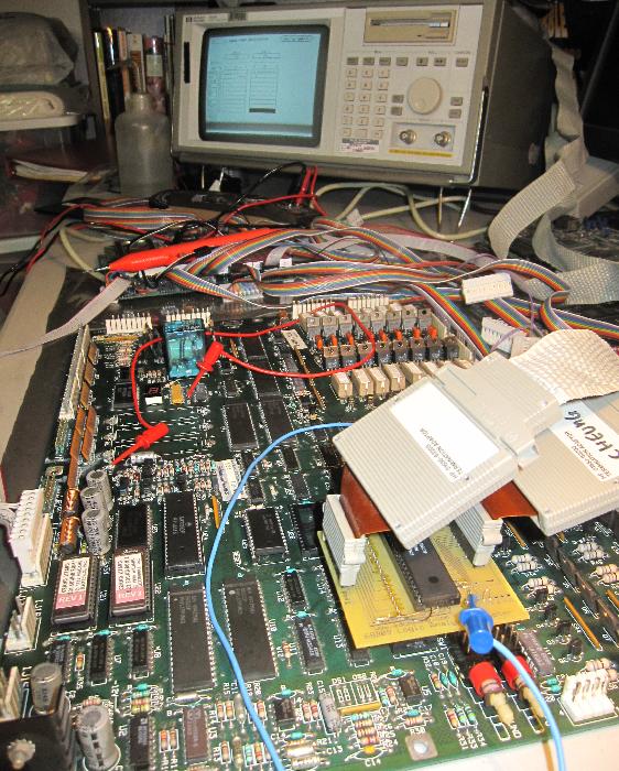
Adapter board in operation on a System 11 board. This allows me to
accurately trace the program execution and better find what is wrong
with a board.
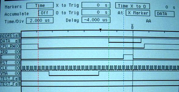
Typical view of Logic Analyzer connected to a CPU chip. The last two lines
are spare signals that the user can clip to the board (blue clip in image above).
Logic Analyzer Adapter for 16 pin DIPs
I had some small amount of space leftover on the above circuit board for the Logic Analyzer, so I added two smaller boards. One is shown here, and allows a LA pad to monitor all 16 lines of a 16-pin DIP IC.
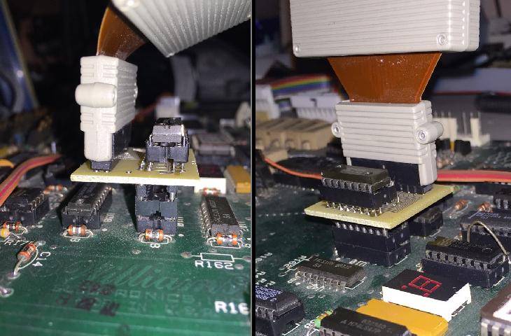
This adapter allows a straight-through connection of a 16 pin DIP and provides a
tap for a LA pod. All 16 pins of the DIP can be easily accessed.
LA screen display with an example test.
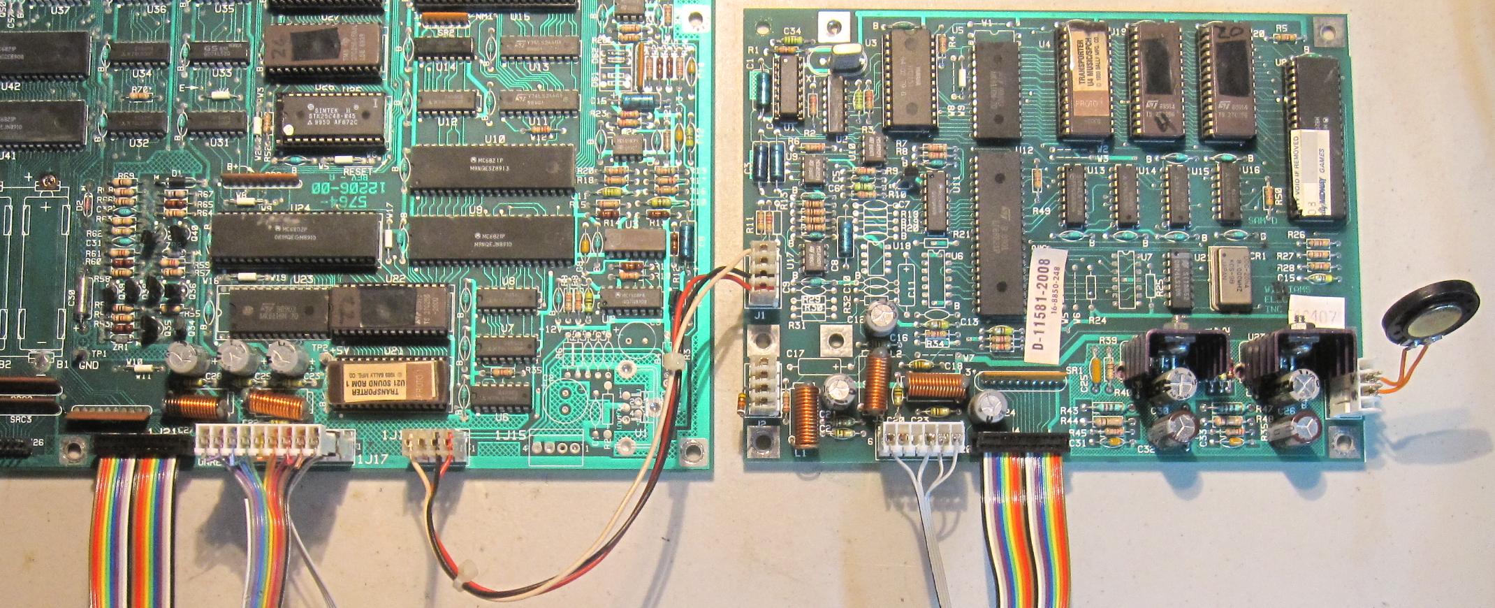
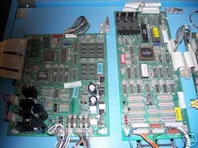
Siamese board setup with
the Logic Analyzer
What is better than a CPU board being observed by a Logic Analyzer? Why two boards of course. After 10 years of repairing boards, I have encountered one or two that pass all tests on the individual components, but still do not boot and run. I needed a brute force way of finding the problem, and imagined a setup where a good reference board was compared step-by-step with the bad board. The setup below shows this configuration.

What is better than a CPU board being observed by a Logic Analyzer? Why two boards of course. After 10 years of repairing boards, I have encountered one or two that pass all tests on the individual components, but still do not boot and run. I needed a brute force way of finding the problem, and imagined a setup where a good reference board was compared step-by-step with the bad board. The setup below shows this configuration.
Twin boards on the Logic Analyzer to find why one does not
work.
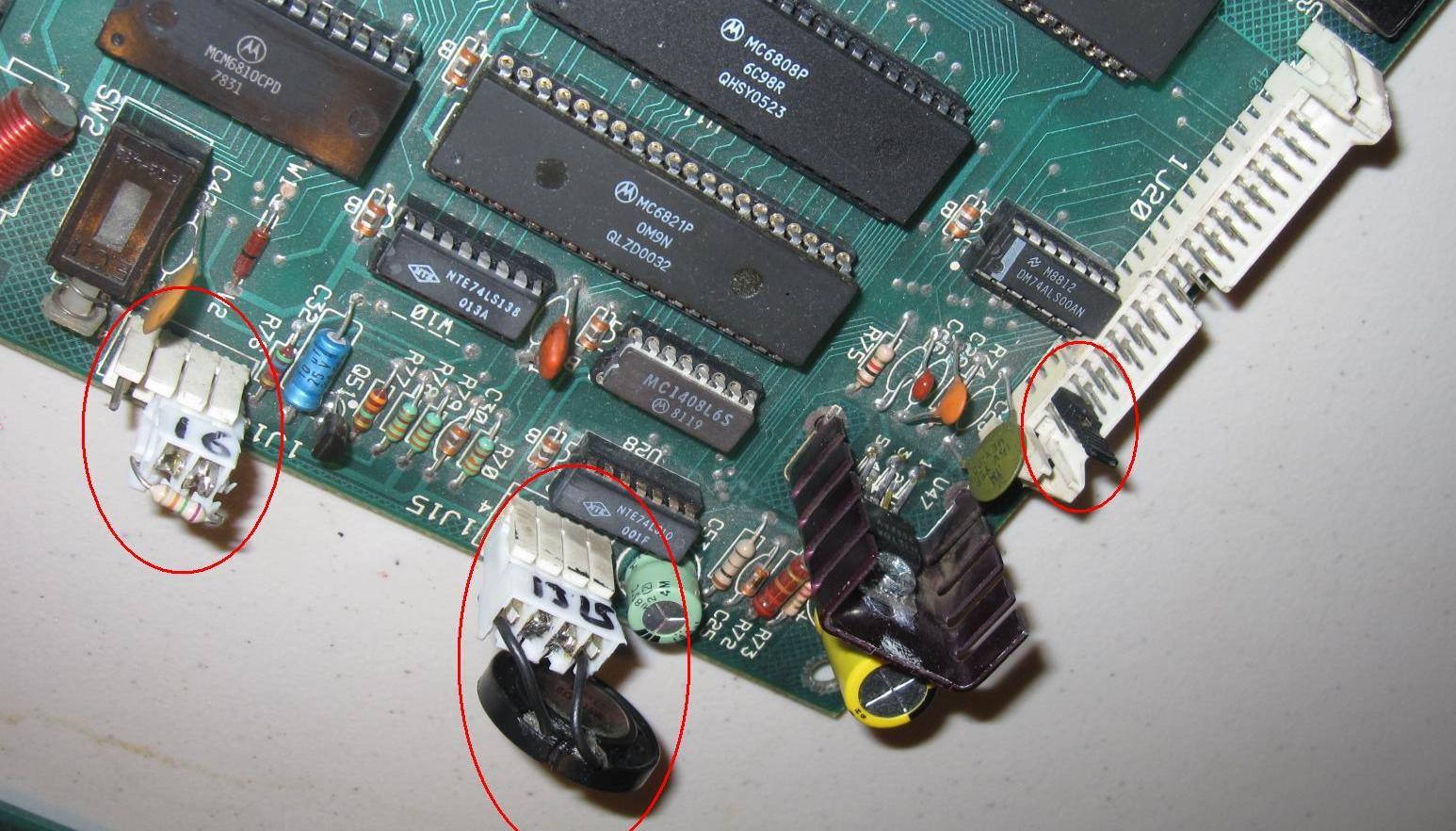
The
crystal oscillator and reset circuit from the master board is used on
the slave board by removing selected components from the power up reset
circuit and the crystal oscillator. They are passed by a
three
wire bridge shown as the grey cable in the image above. This
grey
cable plugs into the sound CPU socket.
With this setup the two boards will run precisely in sync and their data and address busses will have identical contents (using identical copies of the game ROM of course) until the bad board deviates. By inspecting the data and address busses, we can see why the bad board has failed.

With this setup the two boards will run precisely in sync and their data and address busses will have identical contents (using identical copies of the game ROM of course) until the bad board deviates. By inspecting the data and address busses, we can see why the bad board has failed.
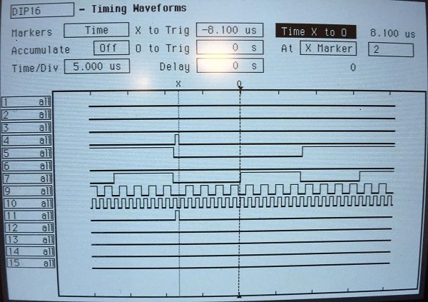
Screen snap of the Logic
Analyzer for the Siamese setup
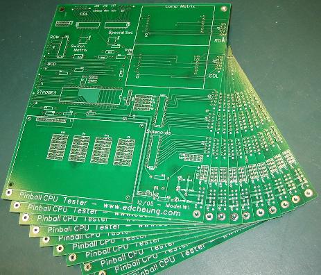
Click here for the next page: Williams PIC68 CPU Diagnostic Test Module
Development of code for the Williams CPU Boards
The
above screen shows an example output of the siamese setup.
The
first box shows a write to ram location 0x9B and 0x9C with the number
0x2100 (big endian). The second box shows a read from that
same
location, and we see the same data coming out of RAM.
However, on
a second read a few clock cycles later, this data is now 0x9B82.
After replacing the RAM chip and seeing no difference, I
realized
that the problem was with the RAM power circuit. Indeed
repairing
that issue fixes the bad board. Success.
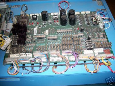
Logic Analyzer with a System 3-7 System
I find the System 3-7 series harder to debug as they have the simpler diagnostics and the finicky interboard connector. It occurred to me that the entire bus is available on the Driver Board, and that I could solder in a set of Logic Analyzer pods to debug any CPU board that fails to boot or has problems.

I decided that ribbon cables would be the neatest way to go and soldered in a 40-wide strip to the back of the Driver Board. The LA adapters then plug into that and the short stub of ribbon is out of the way when not in use.

Logic Analyzer display during a generic read/write interval.
From the above screen we can catch a write from the CPU (at the "X" marker) to address 0x3002. We can see that the waveforms are consistent with the writes/reads occurring at the falling edge of the Phase 2 clock and agrees with the 6800 data sheet.
Using two pods (each 16 channels), I have four spare inputs left over. These can be used by monitoring other signals so that I can better diagnose problems. For example, on one System 3 board, I can tell that an intended write with the data "0xff" actually shows up as an "0xe" on the databus. By hooking one of the spares to the output of the PIC68 CPU emulator, I can see that the problem is in the 8T28 bus transceiver (IC9).
PIA focused Logic Analyzer adapter
There are times when I need to know why a particular PIA is showing a malfunction. Unfortunately, they have three chip selects and that makes it tricky to know exactly when it is being addressed. It is for example not easy to use a scope to trap a write or read. Even with my CPU chip logic analyzer adapter, as some of the decoding and address lines to the PIA could be broken. To address this, I decided to make an adapter specifically for the PIA, but to make it more universal, I decided to build it into a 40-pin IC test clip. This allows me to check any PIA even if it is original and soldered into the board.

This is the IC test clip with the ribbon cable to the Logic Analyzer
I purchased a 40-pin 0.6" wide test clip on Ebay for about $12, and found one that did not have mushroom caps on the pins (pins protruding were straight shaft). This was important so I could mate it to a row of sockets and then soldered to the exposed pins. This allows me to pull the sockets off and reuse the clip with a different set of cables.
One of the 16 inputs is leftover as a spare, and that is connected to the minigrabber shown above. This allows me to monitor an output pin or the IRQ, and be able to trigger on it. This way I can catch writes to an IO port or other similar activity.

The above display shows a sample run with a working CPU board. At the 'X' marker, you can see CS go to '5' (binary '101'), which is the correct configuration for Chip Select to address the PIA. At that moment, the R/W line is low, showing a write. The RS lines show the register selected in the PIA (0). The databus contents is 0xFF (DATABS line). So this is a write by the CPU into register 0 with the data 0xff. You can see that shortly after the falling edge of the E clock, the Data and control lines change, marking the point where the CPU is doing the next bus transaction.
Update: I figured out how to dump the contents of the sampled buffer into a file so that I can analyze on a PC.
Other uses of the Logic Analyzer with a CPU board

The Logic Analyzer can also be directed plugged into
the CPU board to investigate the commands sent to the sound board.
The board at the bottom of this image is explained below.
Logic Analyzer with a System 3-7 System
I find the System 3-7 series harder to debug as they have the simpler diagnostics and the finicky interboard connector. It occurred to me that the entire bus is available on the Driver Board, and that I could solder in a set of Logic Analyzer pods to debug any CPU board that fails to boot or has problems.
Logic Analyzer connected to the Driver Board of a System 3-7.
I decided that ribbon cables would be the neatest way to go and soldered in a 40-wide strip to the back of the Driver Board. The LA adapters then plug into that and the short stub of ribbon is out of the way when not in use.
Logic Analyzer display during a generic read/write interval.
From the above screen we can catch a write from the CPU (at the "X" marker) to address 0x3002. We can see that the waveforms are consistent with the writes/reads occurring at the falling edge of the Phase 2 clock and agrees with the 6800 data sheet.
Using two pods (each 16 channels), I have four spare inputs left over. These can be used by monitoring other signals so that I can better diagnose problems. For example, on one System 3 board, I can tell that an intended write with the data "0xff" actually shows up as an "0xe" on the databus. By hooking one of the spares to the output of the PIC68 CPU emulator, I can see that the problem is in the 8T28 bus transceiver (IC9).
PIA focused Logic Analyzer adapter
There are times when I need to know why a particular PIA is showing a malfunction. Unfortunately, they have three chip selects and that makes it tricky to know exactly when it is being addressed. It is for example not easy to use a scope to trap a write or read. Even with my CPU chip logic analyzer adapter, as some of the decoding and address lines to the PIA could be broken. To address this, I decided to make an adapter specifically for the PIA, but to make it more universal, I decided to build it into a 40-pin IC test clip. This allows me to check any PIA even if it is original and soldered into the board.
This is the IC test clip with the ribbon cable to the Logic Analyzer
I purchased a 40-pin 0.6" wide test clip on Ebay for about $12, and found one that did not have mushroom caps on the pins (pins protruding were straight shaft). This was important so I could mate it to a row of sockets and then soldered to the exposed pins. This allows me to pull the sockets off and reuse the clip with a different set of cables.
One of the 16 inputs is leftover as a spare, and that is connected to the minigrabber shown above. This allows me to monitor an output pin or the IRQ, and be able to trigger on it. This way I can catch writes to an IO port or other similar activity.
Logic Analyzer display with the PIA adapter.
The above display shows a sample run with a working CPU board. At the 'X' marker, you can see CS go to '5' (binary '101'), which is the correct configuration for Chip Select to address the PIA. At that moment, the R/W line is low, showing a write. The RS lines show the register selected in the PIA (0). The databus contents is 0xFF (DATABS line). So this is a write by the CPU into register 0 with the data 0xff. You can see that shortly after the falling edge of the E clock, the Data and control lines change, marking the point where the CPU is doing the next bus transaction.
Update: I figured out how to dump the contents of the sampled buffer into a file so that I can analyze on a PC.
Other uses of the Logic Analyzer with a CPU board
The Logic Analyzer can also be directed plugged into
the CPU board to investigate the commands sent to the sound board.
The board at the bottom of this image is explained below.
Click here for the next page: Williams PIC68 CPU Diagnostic Test Module
Development of code for the Williams CPU Boards
Testing Sound Boards
Interconnection with sound board (click for big image).
The above diagram shows how the System 11 Sound board connects to the test setup. Both the D-11581 and the D-11298 sound boards interconnect with the same harness set.

Power 'Tee' for the sound board
I made a special 'Tee' cable to provide a power tap for the sound board. It is shown in the photo above, partially demated to show the construction. The top colored ribbon goes to my CPU tester, while the grey is to the sound board. The black plastic is a double male (board type) connector that allows the top connector to plug into the top of the middle one.
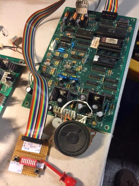
1J21 command simulator with a Jokerz sound board.
The 1J21 connector on the CPU board sends sound/music commands to the external sound board, and I built a small command generator (shown above) to be able to test without a CPU board. All that is needed is the conventional 5/12/-12V supply. With the logic analyzer, I can see the byte sequence to send, and the board can be completely tested with this small fixture.

Schematic of sound board command generator.
Just some switches and a pull up resistor pack RP1.
Video is in the image below.
One issue with testing sound boards is that quite often they require multiple AC voltage sources that are stacked to form Center Tapped outputs. For example, the pre-DCS WPC audio board needs 24Vac that is Center Tapped. Using the discarded transformer from a large UPS, I was able to put together a supply that offers great flexibility.

Multi-output transformer from an old UPS. My trusty variable
transformer (blue box) is in the background.
I know that one winding of this transformer was designed for 120Vac, so we can use that as the primary. It was now a question of what other winding ratios this transformer had and if any are in the useful range.
An important tool for this kind of investigation is a variable tranformer like the one you see in the image above (blue box). It allows you to gradually raise the line voltage for tests like these.
I first started by measuring the inductance of all the windings and using a DVM to see which windings were isolated. The primary needs to have an inductance of at least several hundred mH. This will keep the quiescent magnetizing current down to reasonable levels. Once that is determined, I applied the output of the variable transformer to this winding with a current meter in series. I could see less than 10mA of current flowed once I cranked the voltage up to the full 120V (make sure all output wires are not touching). Now that the transformer could be safely powered from line voltage, it is a simple matter of measuring the output voltage and phasing on all the other windings. I then mounted a barrier strip to the transformer and wired everything to it for easy access. The 120V leads are terminated with the white pair visible above, which lead to a 120V power plug. Incidentally, this power plug is from a discarded Christmas lighting set which has two integrated tiny fuses. I then stacked the resulting five windings to get me a variety of outputs depending on which taps I used. I know can have 20VCT (20Vac total, Center Tapped), 16VCT, 56VCT, and many other assymetric combinations. This will come in very handy in future audio board tests.
Test of System 7 sound board (Black Knight)
Testing plasma display boards
Plasma display board being tested.
System 11 Display Data Tester
The System 11 displays have two rows. The top row is alphanumeric, thus it is able to display numbers as well as the complete alphabet. The bottom row is numeric only for 11A and B, but alphanumeric for 11C. Each row is 16 digits wide, so a total of 2x16 of display data. My desire for this tester is to display a particular row and column to isolate what is happening with the control lines. This examination and use is not convenient to do with the high-voltage displays, and I thought it would be too expensive to buy both types of LED displays as diagnostic tools (about $300 each). I decided to make a single digit alphanumeric display. I could then use it to display the information in a particular row and column of the larger display.

The display data tester
connected to a System 11A board.
"HIGHEST SCORES" is being output by the board
and the first two columns are displayed.
The columns are selected by the blue/green jumpers.
"HIGHEST SCORES" is being output by the board
and the first two columns are displayed.
The columns are selected by the blue/green jumpers.
I started the project by looking for an inexpensive single digit alphanumeric LED display, but found that it was cheaper to buy them as twin digits. In looking at the schematics, it was also clear that the easiest thing to do would be to show both the top and bottom digits of the selected row(s). The user is able to select which two columns of the 16 to display.
The image above shows the completed tester. It connects to 1J22 and 1J3 for the segment information, and the two columns selected for display is controlled by connecting the blue and green jumpers (connecting to 1J1 for the left 8 digits and 1J2 for the right 8). It can work for any System 11 board but it requires the changing out of four of the chips to go from 11AB to 11C. This is due to the data difference between the generations of boards. System 11C board have all their segment data inverted from the previous generations.
The video below shows the display scrolling "HIGHEST SCORES".
- Schematic of Display Data Tester
Display Data Tester isolates the data from two of the 16 columns of the display.
The flashing is because this video is being played in slow motion.
Testing Power Supply Boards

I also built a test setup for the System 9/11 power supply boards. They include an AC multi-output transformer (left) for feeding the low voltage sections, and a connection to my variable transformer for the high voltage circuits. This latter arrangement allows me to turn the input voltage up gradually to prevent damage in case of a fault, and allows me to check how well the board regulates the output high voltage. These plug into the unusual 3x4 pin 3J1 connector.
Part of the trickiest items to troubleshoot on this power supply board is the high voltage. It is a linear regulator and fused by a tiny 1/4 Amp fuse. Almost any kind of failure can easily cause you to burn through many fuses during a repair.

Using a resistor instead of the high-voltage 1/4 Amp fuse.
I hit on the idea of using a large
resistor for the fuse. This would offer a way to limit the
current during the repair. A properly working high voltage supply
shows that it draws around 20-25mA rms. Using a 1.5k resistor
would drop about 35Vac across it. This would work fine as the
normal input voltage for the board is 90Vac, and my Variac can output
from 0 to 125V. I soldered a 1.5k 1W resistor across a blown fuse
and that allows me to easily insert and remove it. At full idle
current it dissipates about 0.8W. Testing shows this approach is
a very good and safe environment to test the regulator.
Checking out the solenoid circuits for safe power up
Due to the high power circuits they contain, pinball machines can sometimes require great care when powering up an unknown machine or configuration. One such situation is the solenoid power. If a playfield switch is shorted closed (along with possibly an incorrect fuse), power could be enabled continuously to a number of solenoids. The result can be melted coils, burned components, or even a fire. I have repaired numerous boards that have complete holes burned into them. I have always thought that it would be good to easily put in a way to checkout a newly acquired machine. One way would be to replace the solenoid circuit fuse (F2) with another component that increases its resistance if current through it is increased. After some thinking about it I realized that incandescent bulbs do this, and I decided to try this idea.
Some background, with the original 2.5 Amp F2 in place, I measured about 0.27 Amps of standby current on solenoid power. Actuating a pop bumper caused 4.2 Amps of steady state current. Since the fuse is slow-blow, this would have to persist a few seconds before blowing it. I was able to keep the coil on for two seconds without blowing the fuse. The unloaded solenoid bus measured 30.8V, and the pop bumper coil measured 3.8 ohms on my testbench.
My first try was to check to see what I had in storage and found that the #89 is the highest voltage bulb I have. It is rated for 13V and draws 0.58 Amps at that voltage. This is a resistance of 22.4 ohms at full brightness. However, when cold I measured only 1.7 ohms. That is an increase of better than 10x! Since the solenoid voltage is about 30V on Space Shuttle, I decided to use two #89s in series and assembled the prototype with some alligator clips. The results show that the current limiting effect was too strong and the pop bumper would not pull in.

Test lamps in place of F2.
For my second try, I purchased a #315 bulb. It is rated for 28V, and 25W, allowing a current of almost one Amp. Cold resistance is about 2 ohms. That worked better as can be seen in this video. When in use make sure that the bulb glows dimly with no solenoids activated (no shorts), and that the coil pulls in weakly when activated (no shorted coils or backwards diodes). It is also a positive sign if you can manually move the coil and it stays latched. This system should work for board sets that use 30V solenoid power such as System 7 and later.
2532/2732 Adapters
Some early System 3-7 CPU boards use 2532 ROMs. These are similar to 2732s except for a slightly different pinout, and were originally made by TI. My PROM programmer, the Dataman S4, does not have an entry for the 2532, so I decided to make adapters to program these ROMs. I used a wire-wrap socket and a conventional socket stacked on top of each other. This is shown on the left in the image below. I found that using the Toshiba setting for the 2732 worked best on my Dataman.

Adapters to allow a 2532
to be plugged into a location for a 2732 (left)
and using a 2732 into a location meant for the 2532 (right).
Links
A note on System
9 to 11 conversions (sound)and using a 2732 into a location meant for the 2532 (right).
Since
I was making the adapter anyway, I decided to make the reverse adapter.
Namely one that allows the use of a 2732 ROM in an
application
requiring a 2532. That is shown on the right above.
Links
- How to make the adapter (Bob Roberts).
- Another diagram (Classic Computers).
In July 2016, Joe George sent me his findings on using a System 11 in a Space Shuttle
Since
my System 9 CPU Board quit working, I converted a base System 11 board
to work
in System 9 following the instructions at the end of the System 9
Troubleshooting Guide I found at http://gamearchive.askey.org/Pinball/Manufacturers/Williams/pdfs/pinball_troubleshooting_sys9.pdf.
It turns out though the memory map in the manual is wrong. It implies
that the
4 2732 speech ROMs would be stacked in order (U4, U5, U6, U7) into a
27128 ROM
for the System 11 Sound ROM at U22. However, the memory map is wrong,
and for
some reason the Space Shuttle manual I have doesn’t include a schematic
for the
speech board, so I couldn’t tell that the conversion doc was wrong.
I
found a Speech board schematic in the manual for Sorcerer and it said
the
memory address space was occupied by (in order) U7, U5, U6, U4. I
stacked the
4K speech ROM images I had from the speech board in that order and
reburned a
27128 ROM, and my speech works great now!
In December 2019 I found this ROM set for testing various Williams systems. One set focuses on the System 3-7 series and consist of a set of about two dozen ROM images. The original intention was to burn a ROM for each test and put that into the IC17 spot on the board to run the test. I immediately thought of building an adapter board with DIP switches to select the test. Reading further I saw that indeed someone had designed a board for this purpose. This design accomodated up to 16 types of tests, but the author of the ROM series had since increased the number of tests to about two dozen, requiring an upgrade to handle up to 32 tests.
The board design by 'barakandl' made me wonder if a conventional perf board (with predefined traces) could work reall well and I decided to try and build a board.

Original design by barakandl shows many horizontal connections. This
made me wonder if a perfboard with bars would make the job easier.

Indeed all I needed to do was to cut two of the bars (near top left)
and a standard perf board will do the job. On the left are the
double ended male pins I use to build adapter boards.

Board completed. The double ended male pins are sticking up
out of the image and plug into some extender sockets and then
into the System 3-6 board under test.

On the 'top' side of the board I mounted a socket for the 27512 PROM
and the five DIP switch module to select which of the 32 test pages
to use.
Since
each original 2316 ROM was 2Kx8, and we want to be able to accomodate
up to 32 of these ROM images, we would need a 64kx8 ROM, which happens
to be the 27512. In looking through my parts bins I saw I had
all
the parts, and completed construction of the above adapter in one
evening.
I next had to obtain the image of the PROM, and I downloaded the package from the pincoder.ca web site. The lowest slot or "00000" of the combined ROM is meant for the original IC17 image from Williams but wide distribution of that would probably violate copyright rules, and is why it is not included in the download. So I copied the bytes over from an original ROM, and combined it into the file from pincoder. In the future, I will make this available here via a link.
After correcting a small error in the board, the combined test ROM worked like a champ. On a known-good System 3 board, I could boot into the standard functions by setting the DIPs to 00000, and then execute Test 1, which is the LED alternate flash test.
Other Notes
The Molex connectors that are used on these boards are often difficult to demate.
I hit upon an idea to make a handle to more easily pull them off without damage. It is to
drill two small (1/16") holes on the ends, and then use some stiff steel wire from a
small paperclip to create a handle. Some care must be taken to not short to the contact,
but the circuit design is such that they are robust to being shorted.

Photo of Molex connector with the added handle.
Other CPU Testers
Photo of Molex connector with the added handle.
Other CPU Testers
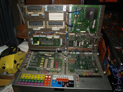
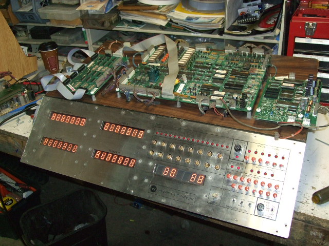
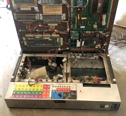
These are Ebay auction
prices and photos I have gathered over the years on these
testers. The Williams factory appeared to have made three
kinds of board testers. One for System 3-7, the second for
System 11 (and 9?), and two WPC testers (WPC89 and WPC95).
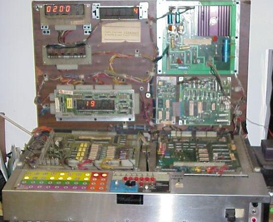
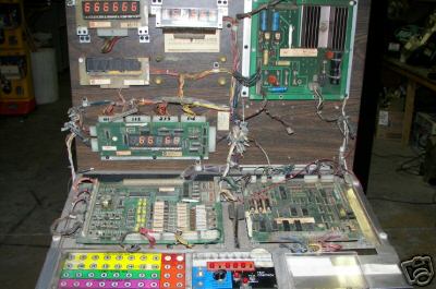
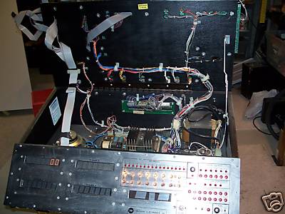
February 2006, this System 3-7 tester (6253871562) was $665+$70.

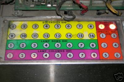
Close-up of the control panel of the above tester.

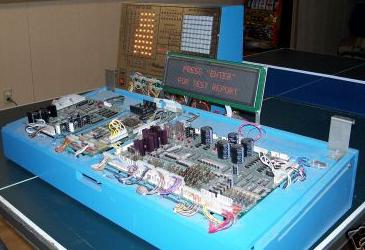
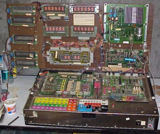
Feb 2006, this System 11 tester (6254290420) was $366+70.
It looks home-made.

Close-up of the test panel. Note lack of solenoid and lamp matrix displays.
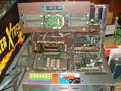
Feb 2006, this System 3-7 unit (6255704954) was $474+shipping.

Closeups of the test panel.
Video of System 3-7 tester in operation.
February 2007, this WPC95 tester (110093911411) was $1500.
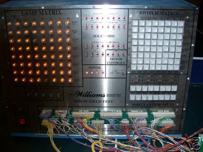
The I/O panel looks like it includes a matrix of lamps (similar to my tester),
and a matrix of switches. One can also see test lamps for solenoids and other
devices.
Close-ups of the above WPC95 tester.

September 2007, this System 3-7 tester sold for an amazing $1200
(170143659660).

In March 2008, this System 3-7 tester sold for $515 (160213461303).
It is highly incomplete.
April 2008, this System 3-7 tester was $688 (130209246482).

June 2008, this System 3-7 tester was $236 (320258934586)
It was missing its boards and the upright panel.
Sept '08, this System 11 tester sold for an amazing $1435 (120300193798).
I am always amazed how much these units sell for compared to my tester.
Nov 2008, this System 11 tester (110312219131) was $550.
July 2009, this System 3-7 tester (140329614857) was $500+$50.

Oct 2009, this System 3-7 tester (250506825123) w/o driver board
was $160 (IL pickup only).

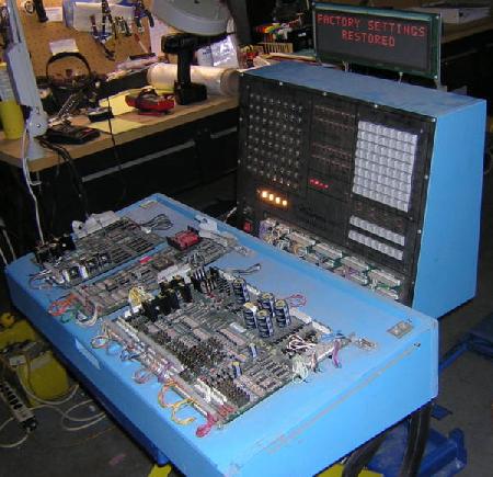
Oct 2009, this WPC89 tester (250506810477) was $635 (IL pickup only).


In Dec 2009, this new WPC89 tester (320457377514) was an amazing $3900.
In March 2010, this WPC-95 tester was $2600 (280476266131).
April 2010: This System 3-7 was $560 (Ebay: 260579868990).
<
August 2016: This 3-7 tester was $1400 (Ebay: 112108025438)
February 2006, this System 3-7 tester (6253871562) was $665+$70.
Close-up of the control panel of the above tester.
Feb 2006, this System 11 tester (6254290420) was $366+70.
It looks home-made.
Close-up of the test panel. Note lack of solenoid and lamp matrix displays.
Feb 2006, this System 3-7 unit (6255704954) was $474+shipping.
Closeups of the test panel.
Video of System 3-7 tester in operation.
February 2007, this WPC95 tester (110093911411) was $1500.
The I/O panel looks like it includes a matrix of lamps (similar to my tester),
and a matrix of switches. One can also see test lamps for solenoids and other
devices.
Close-ups of the above WPC95 tester.
September 2007, this System 3-7 tester sold for an amazing $1200
(170143659660).
In March 2008, this System 3-7 tester sold for $515 (160213461303).
It is highly incomplete.
April 2008, this System 3-7 tester was $688 (130209246482).
June 2008, this System 3-7 tester was $236 (320258934586)
It was missing its boards and the upright panel.
Sept '08, this System 11 tester sold for an amazing $1435 (120300193798).
I am always amazed how much these units sell for compared to my tester.
Nov 2008, this System 11 tester (110312219131) was $550.
July 2009, this System 3-7 tester (140329614857) was $500+$50.
Oct 2009, this System 3-7 tester (250506825123) w/o driver board
was $160 (IL pickup only).
Oct 2009, this WPC89 tester (250506810477) was $635 (IL pickup only).
In Dec 2009, this new WPC89 tester (320457377514) was an amazing $3900.
In March 2010, this WPC-95 tester was $2600 (280476266131).
April 2010: This System 3-7 was $560 (Ebay: 260579868990).
<
August 2016: This 3-7 tester was $1400 (Ebay: 112108025438)
Links
- Leon's System 9 test page.
- Hard to find CPU parts at GPE.
- Okaegi's System 6 tester (scroll down "Williams part").
- Pinout of DE-9/DB-9/IDC RS-232 connector.
- Debugging sound on System 9 (photo of setup).
- System 6 Schematics.
- Mark's guide to Williams System 3-7.
Log
- October 26, 2005 - Purchased first nonworking CPU board for $40 + $10. Previously, I had seen untested units on ebay in the range of $31 (burn damage) to $175 (clean).
- November 7, 2005 - Initial checkout complete. Board is mainly working. Only K1 still missing (on order).
- November 10, 2005 - Completed initial breadboard concepts for CPU tester.
- Discussion
on RGP regarding this device.
- November 25, 2005 - Initial layout of circuit board complete.
- November 26, 2005 - Purchased a second nonworking CPU board for $23+$14 on ebay. When powered up, it passes CPU self-test, and lamp matrix works fine. Further testing in the future.
- December 01, 2005 - Arrival of the finished CPU tester boards.
- December 03, 2005 - Initial testing of the CPU tester complete. Lamp matrix, switch matrix and LCD interface operational.
- December 11, 2005 - Software development of the Microprocessor in progress.
- December 26, 2005 - Software development mostly complete. Kit is made available.
- January 13, 2006 - Initial orders and parts are in. Manual is half written. Assembly of first round of units begins.
- January 21, 2006 - Initial orders complete and ready to ship.
- February 1, 2006 - First use of tester to repair a CPU board.
- February 19, 2006 - A nice endorsement
from Peter regarding the CPU tester.
- February 20, 2006 - Auctions for
two CPU testers on ebay.
- March 14, 2006 - Due to popular demand, I built a second batch of testers.
- March 24, 2005 - System 11 compatibility added.
- August 7, 2006 - First unit sells with BIN on ebay for $500 (item #170016357842).
- July 2, 2007 - Case #6
documented.
Conversion to MOSFETs for the high-side lamp matrix driver.
This board was bought on Ebay for $35 (+$15).
- August 2009 - As of this date, I have successfully repaired more than 50 System 9 and 11 boards. I am glad to say that despite the varied challenges (battery leakage, burns, failed parts, etc), I have not failed to repair a single one. That is about one board per month since 2005.
- August 2009 - Made adapter
board to easily connect Logic Analyzer to a 6802/6808 CPU
chip.
- May 2010 - Added System 3-7 mode to CPU tester.
- October 2011 - Added power supply test fixture.
- March 5 2016 - Added Siamese setup.
- May 2 2016 - Added DIP16 breakout board.
- Jan 22 2017 - System 8 board repaired with tester.
- June 15 2017 - Display Data Tester.
- January 26 2019 - Multi-output Transformer
- May 2 2019 - A way of safely checking out solenoid circuits
- Sept 27 2020 - Logic Analyzer adapter for System 3-7 CPU Boards.
- Sept 28 2020 - Logic Analyzer adapter for PIA chips.
Note:
I have several repaired System 9 and 11 boards for sale, and
I
also repair these boards. Please contact me for details.
(c) 2009 Edward Cheung, all rights reserved.